8/11/2011

 |
 |
|
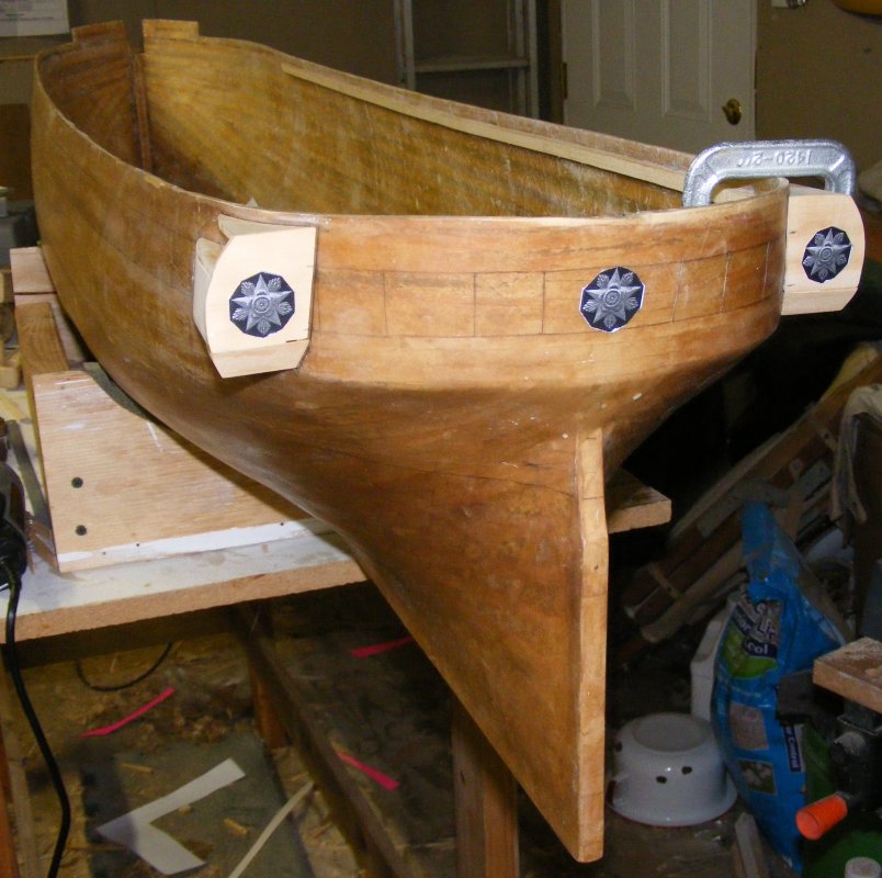
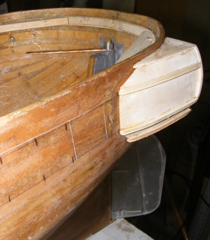
Previous Page | Next Page | Table of Contents click pictures for a larger version March 2009: None of the ship's drawings showed how the bulwarks were constructed, but the folks at the restoration showed me the iron stanchions that are wainscoted over to make the bulwarks. I decided the hull would stop at the waterways with the bulwarks added later and cut the plug back leaving only the sections of bulwarks on either side of the bowsprit standing. I began building the quarter galleries and shaping the stem. I also started making the masts from clear white cedar.
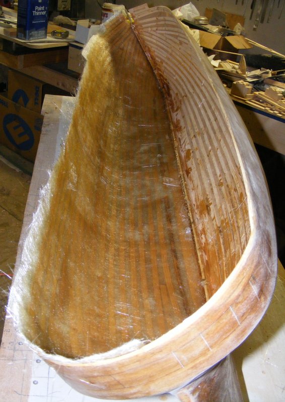
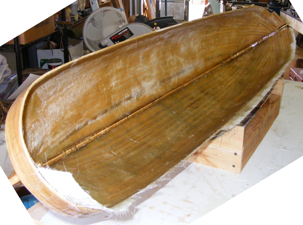
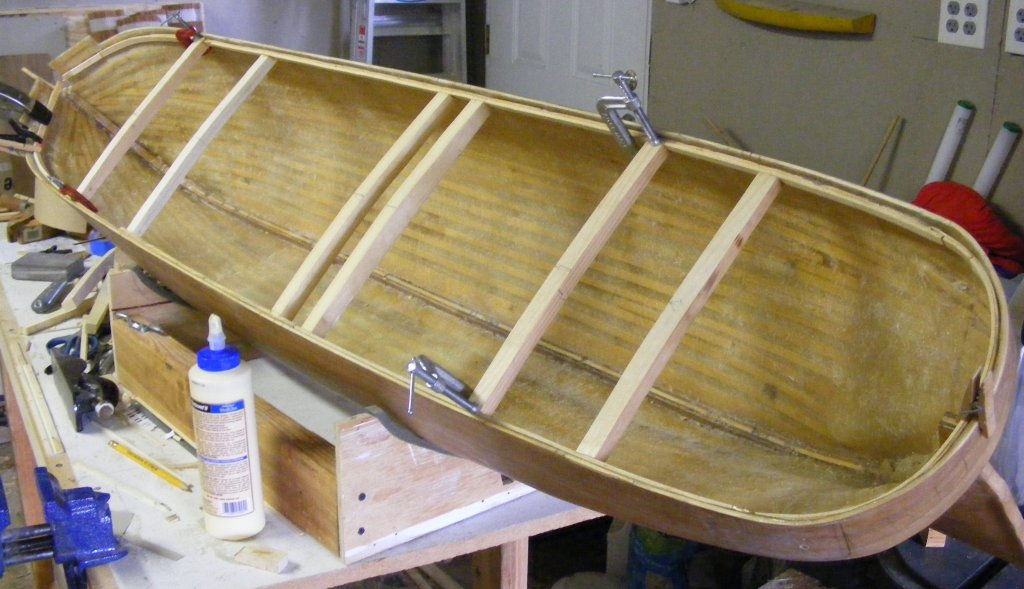
I went along detailing the plug, but I wasn't happy with the effect. It seemed I would spend all this time and energy making something that would be destroyed with no guarantee of success. By the end of March 2009 I opted to glass over what I had and use it as the model's actual hull. In retrospect, I should have striped it down to the keel and forms and started over by planking it up properly. (see the Macedonian work log to see what that means.) April: I worked on prepping it to be glassed and laid a layer of 4oz cloth on the outside on April 4th. Sanding and then another coat of resin went on the 6th. The forms were pulled out of the hull on the 8th. The inside sanded and resin poured in to fill between the battens. On the 9th glass matt was laid in the hull's port side. The 10th matting went into the starboard side - stiffening the hull considerably. The spar deck clamp started going in the same day.
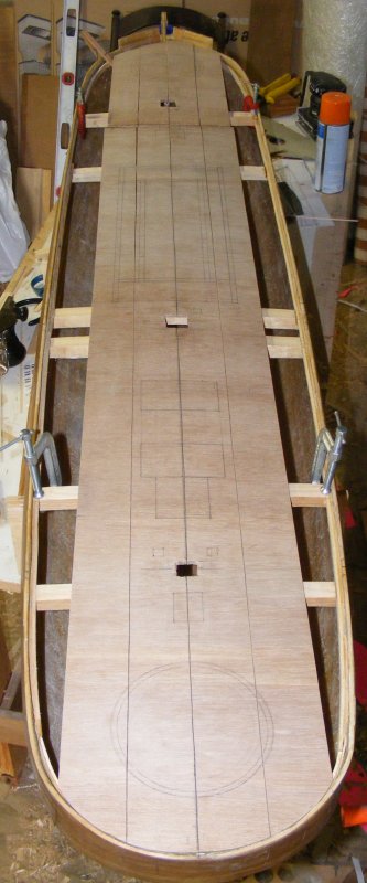
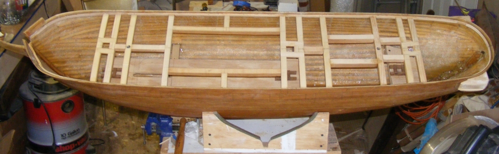
As new, permanent quarter galleries were roughed out, framing went in for the mechanical deck where the RC equipment would be mounted, and the cambered beams for the spar deck. A sub-deck was cut from luan plywood, about 3/16" thick, and the deck arrangement sketched onto it. The sub deck was ripped into 2" wide strips so it could form to the deck camber and the sheer.
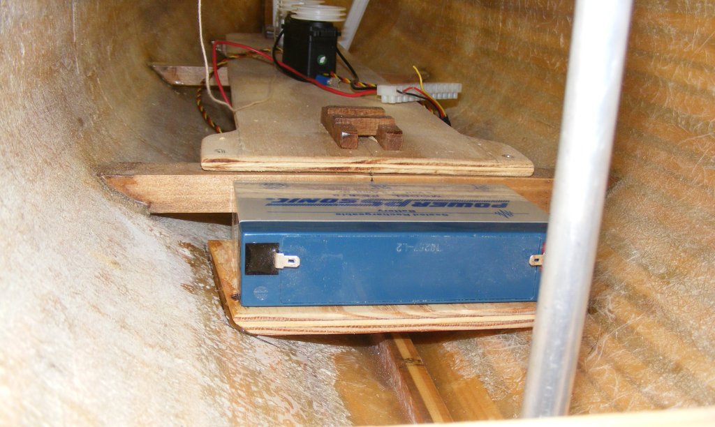
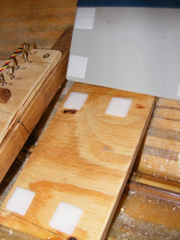
June: The mechanical deck is 5/16" plywood. There are actually three; the largest amidships hold most of the radio equipment, as well as the steps for the fore and main masts. Just aft of this is a small platform for the 6v sealed-lead-acid battery to lay on held by hook-n-loop tabs. Further aft and higher is the aft mechanical deck on which is stepped the mizzen mast and the rudder servo is mounted.
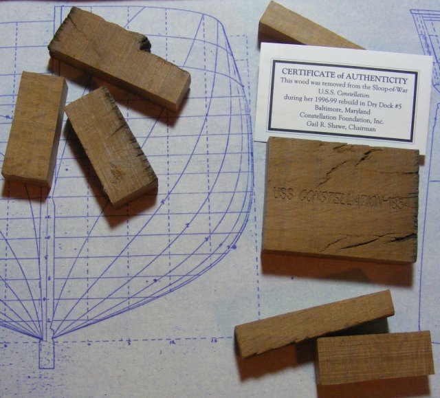
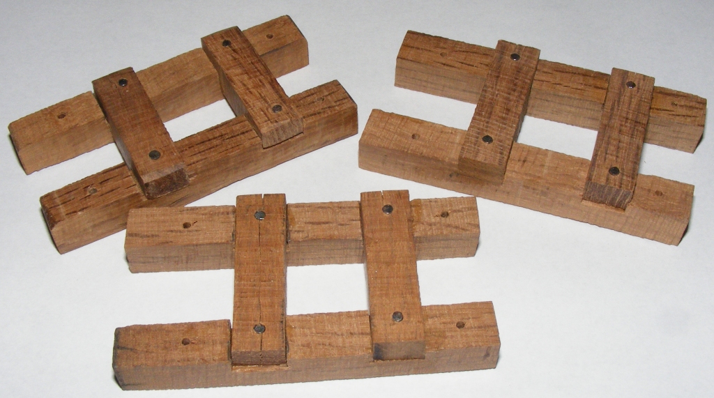
The director of the actual ship gave me some bits of live oak removed during the restoration. I wasn't sure how or where I could incorporate it into the model, so I used it to make the mast steps. Another portion stamped with the ships name will be used as a plaque inside the model with the model's completion date and my name added to it.
More deck framing, mast partners, and tubes for the rods that would hold the detachable ballast to the hull were all installed.
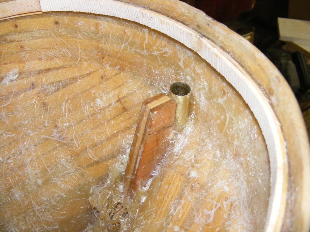
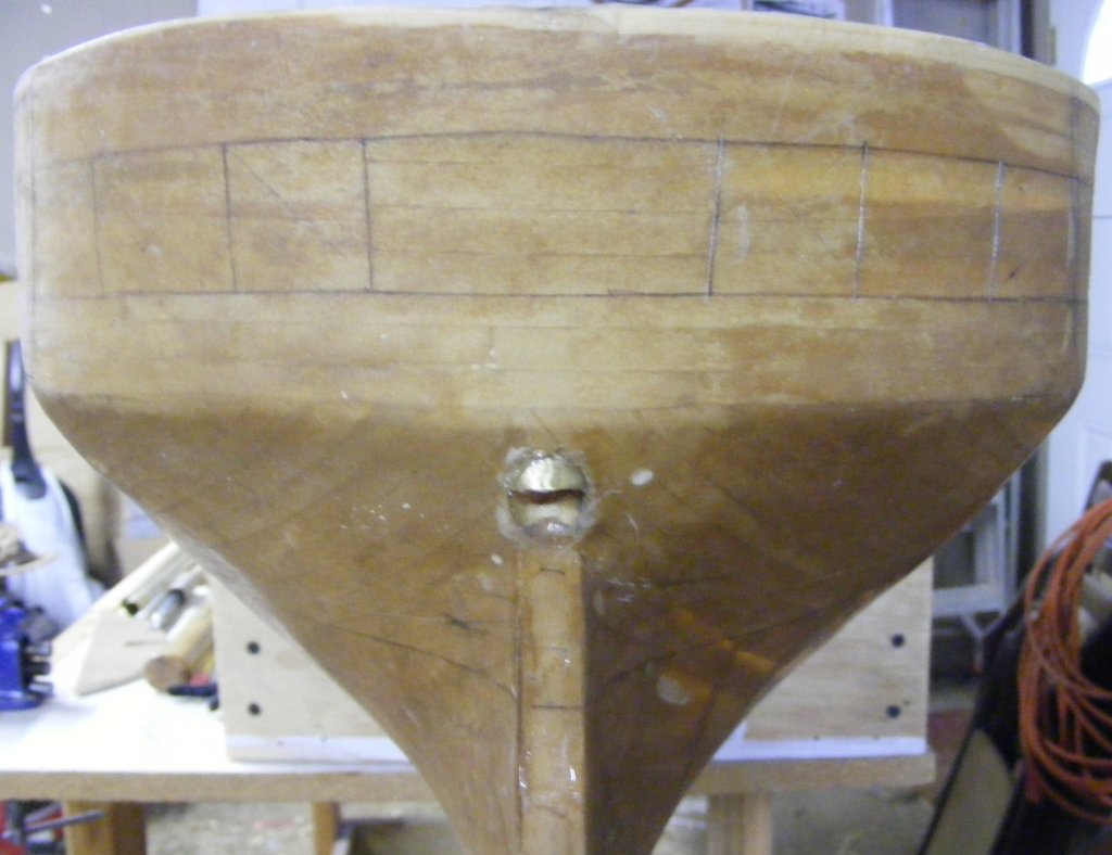
Controls The rudder hole is very close to the transom which means a 'T' bar with a push-pull set-up won't fit; instead, I'll use a traditional tiller arrangement. The hole was drilled and a brass tube epoxied in place showing though the counter slightly. The actual ship has a curved plate here that the brass tube approximates fairly well.
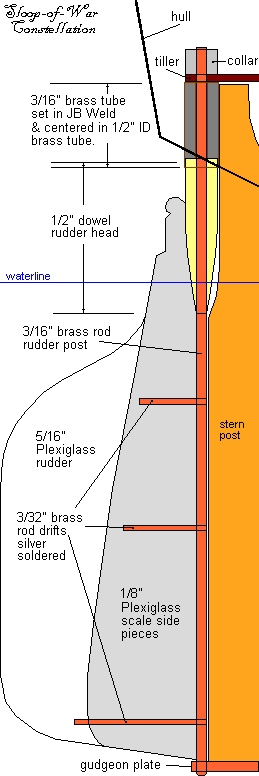
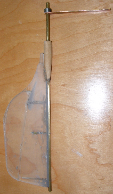
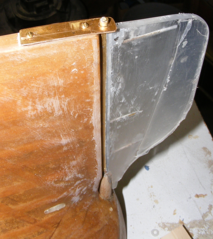
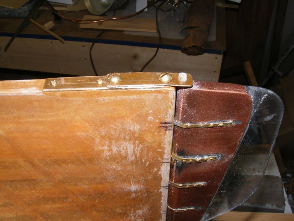
July: The rudder was scanned off the 1:87 plan and scaled up to 1:36 (the 1:36 plan doesn't show the rudder). A Plexiglas rudder of a little more than twice the area was made with 1/8" Plexiglas cheek pieces shaped to the scale rudder. The scale portion is painted and coppered while the over sized part was left clear. The rudder hinges on a 3/16" brass rod that sits in a gudgeon plate at the bottom, and passes through the rudder hole at the top. Three rods pass through the 3/16" rod into the rudder for support. A tiller is attached inside the hull. The rudder hole is filled with JB Weld with a 3/16" i.d. brass tube centered in it to received the rudder post. The head of the rudder is a maple dowel that fits into the socket of the larger brass tube. The pictures should explain it all better than I have..
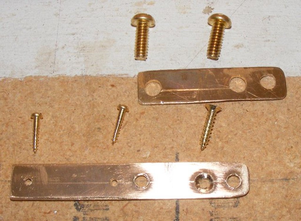
August-September: The gudgeon plate was made easily removable by attaching a copper plate to the keel. The plate is screwed to that with two brass machine screws.
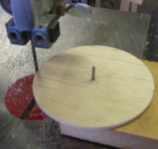
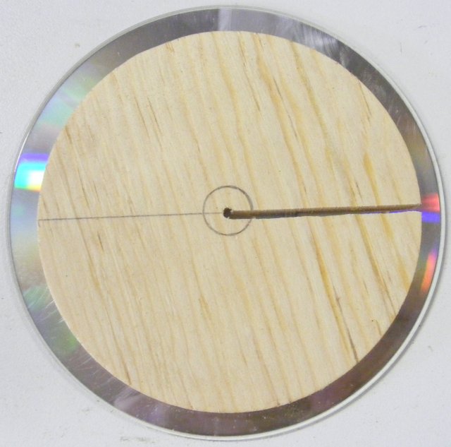
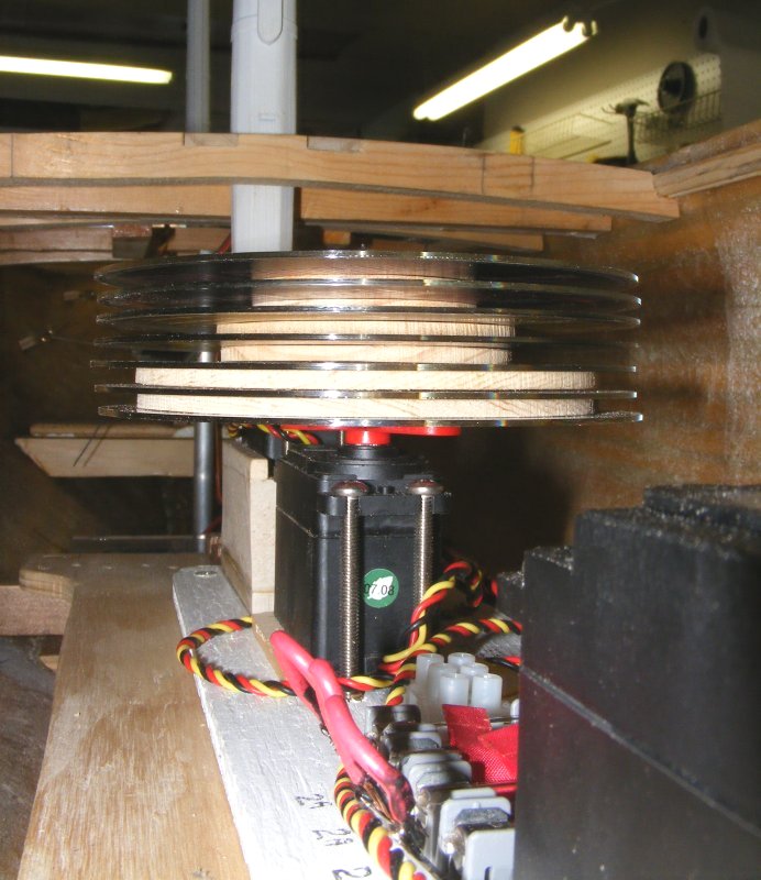
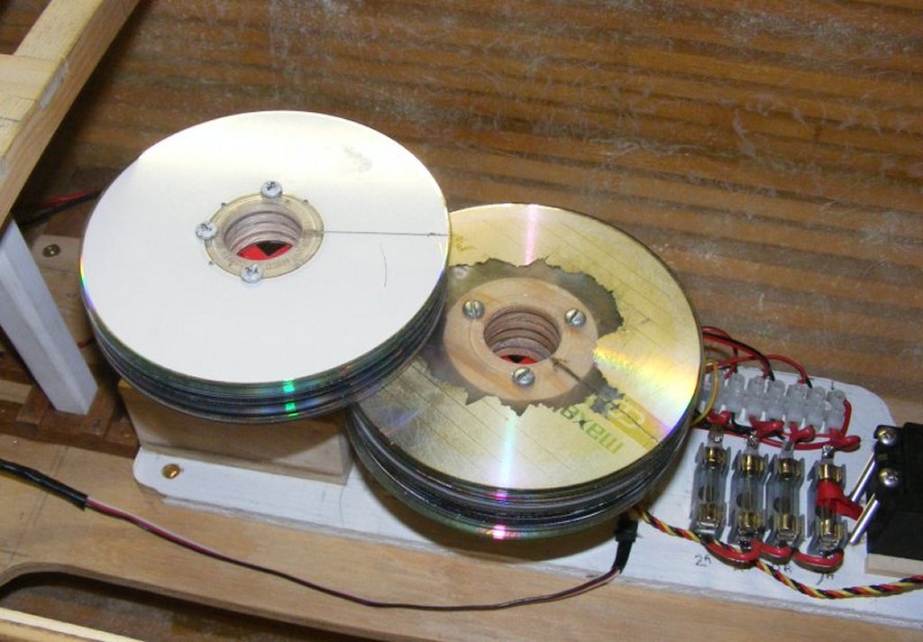
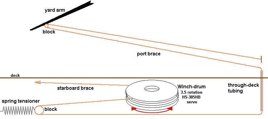
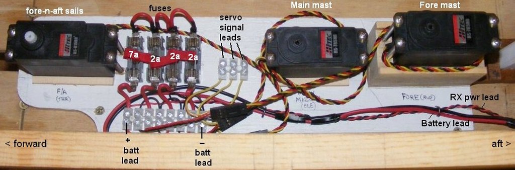
My plan for controlling Constellation is based a great deal on the set-up in Dan's Syren. The braces will be run as prototypically as possible. They will be controlled by winch servos with custom made drums on them. One servo will operate the fore mast yards, the other will operate the main and mizzen yards together - this will allow for boxing the fore mast sails separately when tacking. The yards actually controlled will be the fore and main course yards and tops'l yard, and the cross jack. The winch drums are 1/8" styrene disks with compact disk flanges separating them. Each yard has two disks, for a port and a starboard brace. The disks are different sizes because the braces attach to the yards at different distances from the center making each brace a different length. Each brace comes of it's drum and goes to a turning-block mounted on a spring on a post; this maintains tension of the braces to prevent snags and catches. All the sail servos are mounted on a pallet that can be removed as a unit if need be.
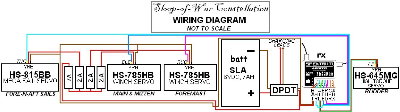
The simplest set up for brace control would be to use an arm with the braces attached to the yard the same distance from the center as they are on the servo arm. Because this arm's length is limited by the interior width of the hull, the braces wouldn't attach to the yard where they would prototypically be. The winch/disk set-up with it's 3.5 rotations basically fits a longer arm in the hull. The trick is that while the winch is working in circles, pulling an inch on one side, and paying an inch on the other - the brace, from the last block to the yard is a line, a vector, changing it's length and angle, ie: the braces don't work evenly on either side. ok, I think in images, not numbers, so understanding it is pushing the envelope - explaining it is another thing entirely. Let's just say that when the yard is squared, the braces are taut. As it's braced to one side, the paying out brace will go slack. Slack is bad - we don't want slack, so the springs in the system take up that slack and keep things taut. Wiring schematic and actual servo set-up on it's pallet:
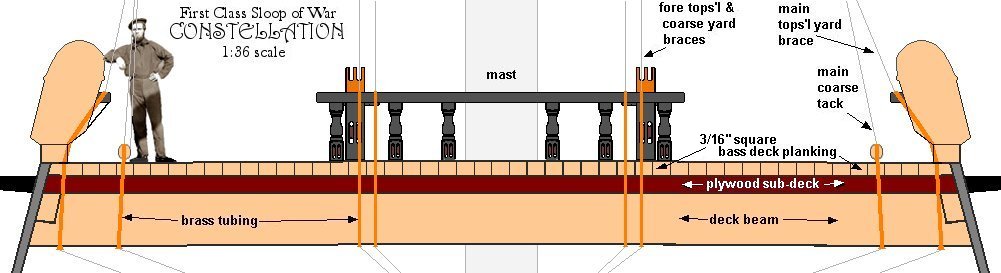
The braces will pass through the deck at their belaying points though brass tubing hidden in the bulwark and/or behind coils of lines
I had to go with RC because trying to train the local squirrels to sail the model didn't work; they just gnawed on things and filled the hull with nuts.
|
||
 |
 |