

12/17/2024

 |
 |
|
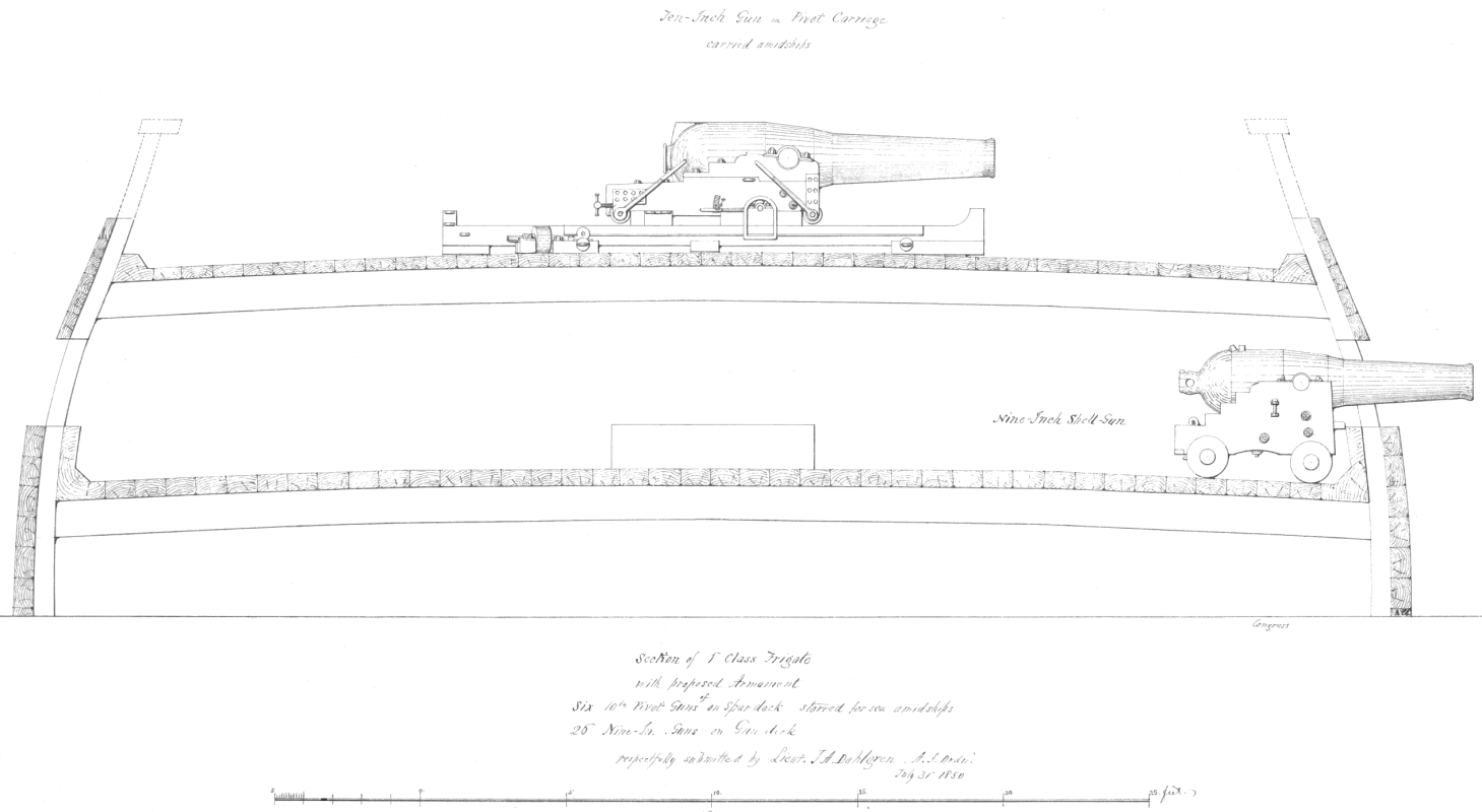
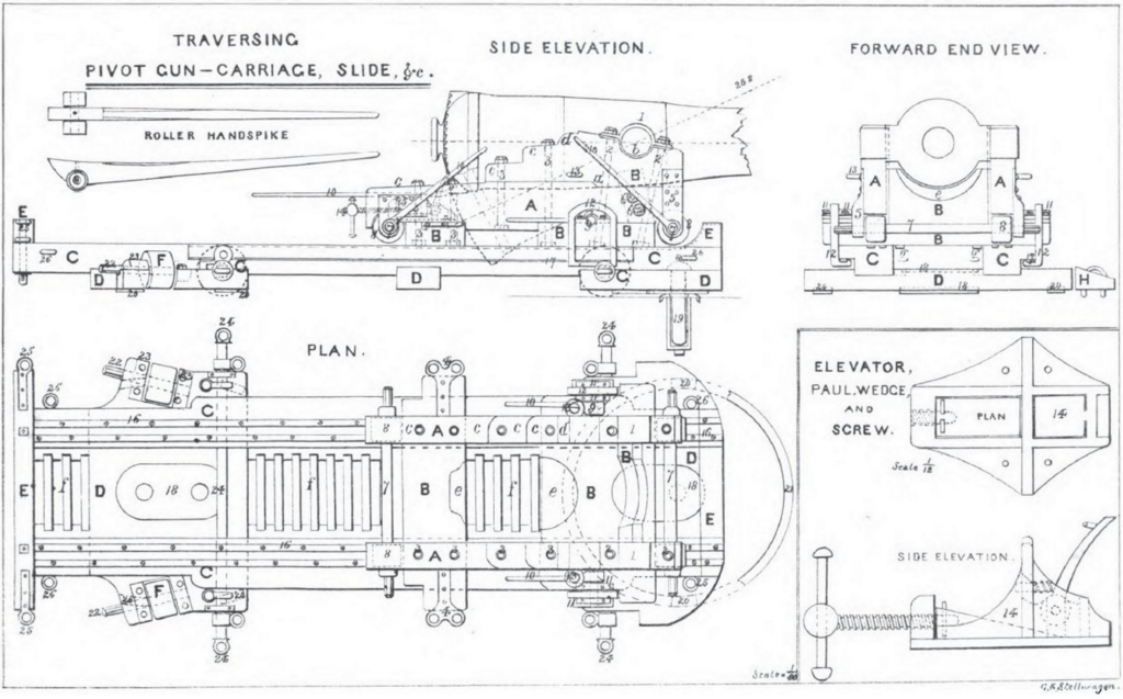
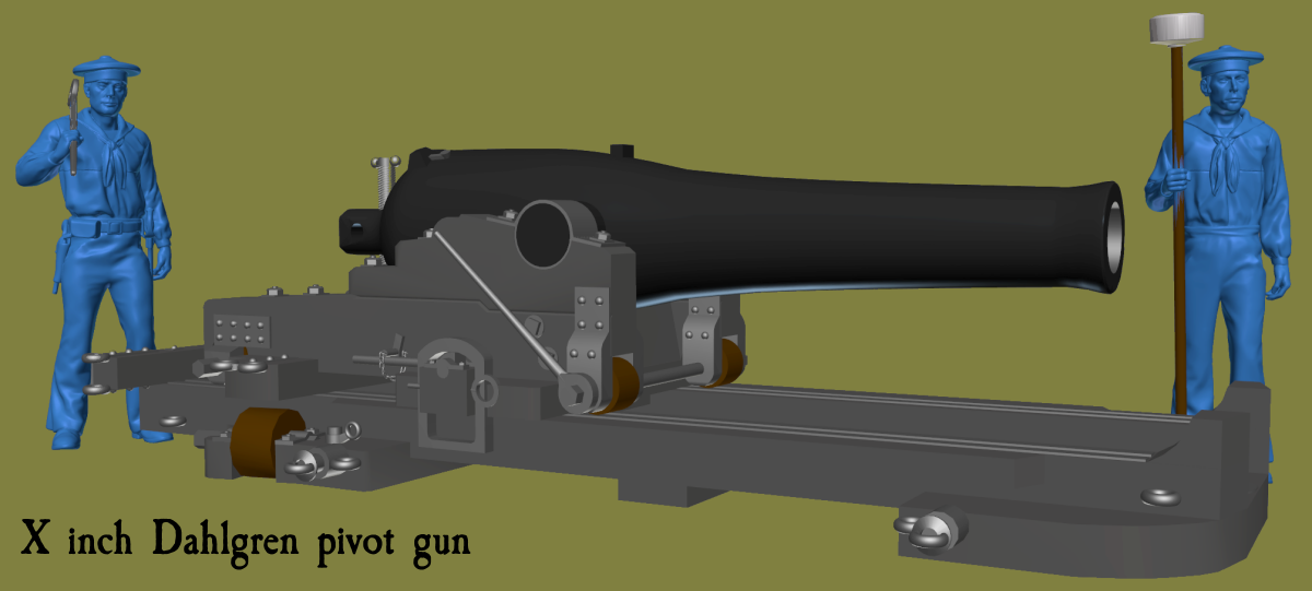
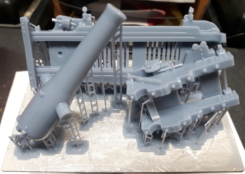
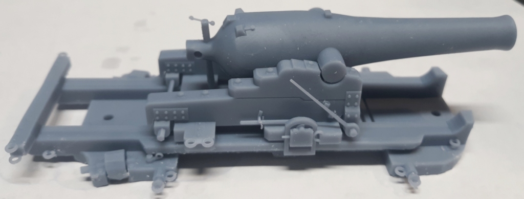
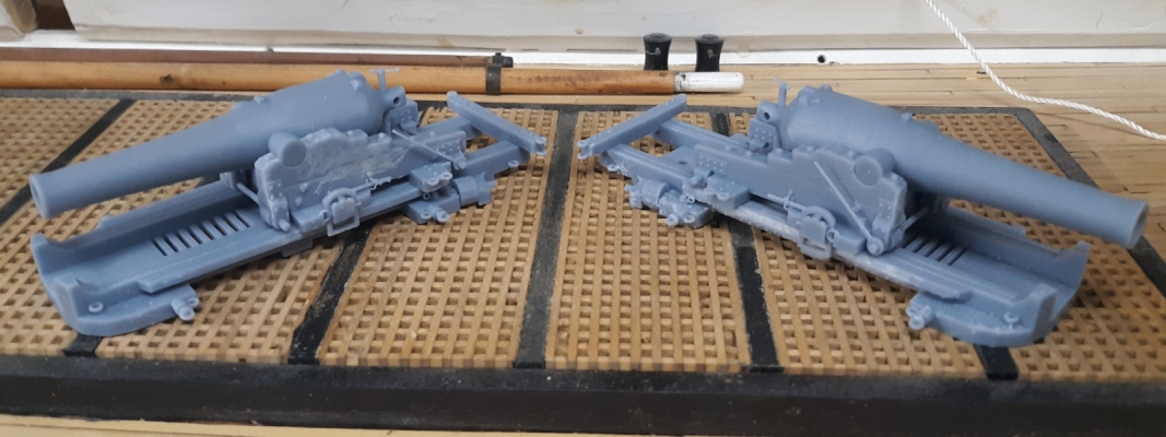
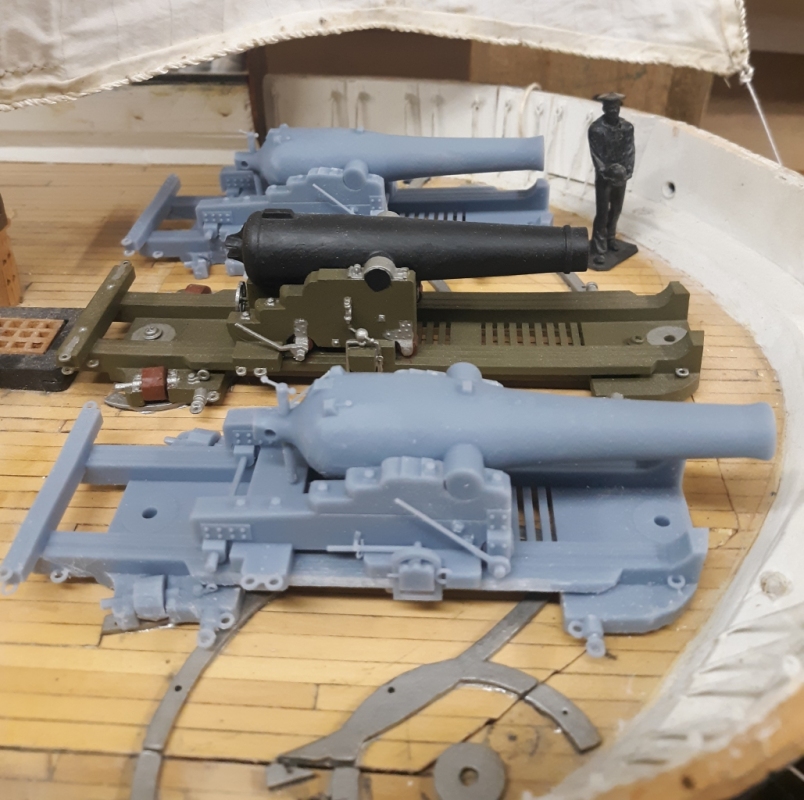
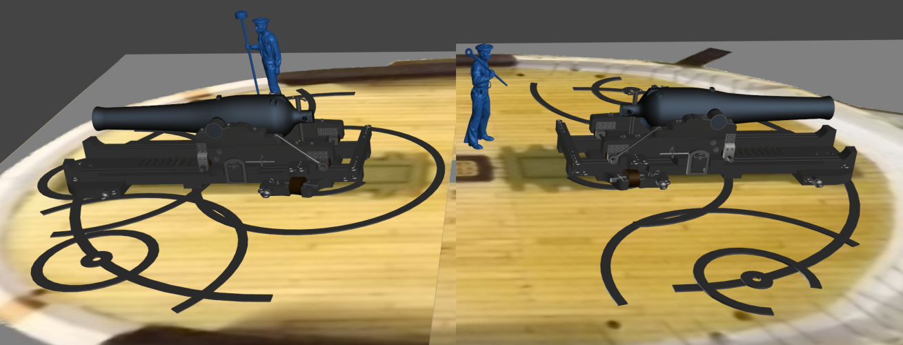
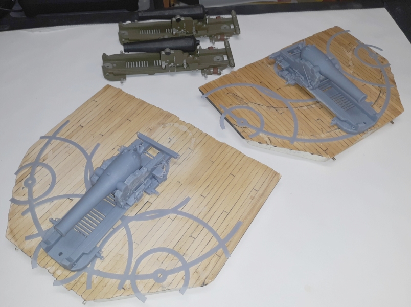
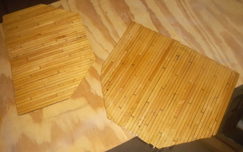
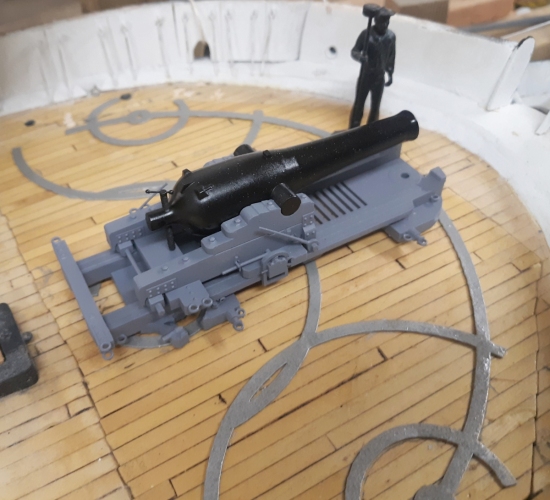
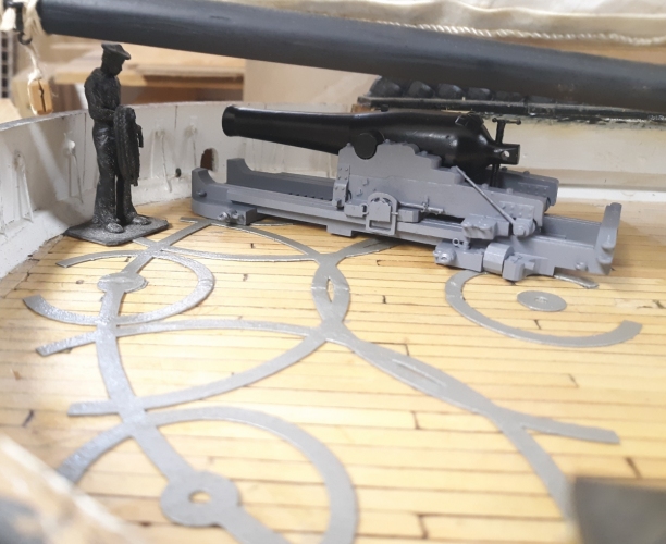
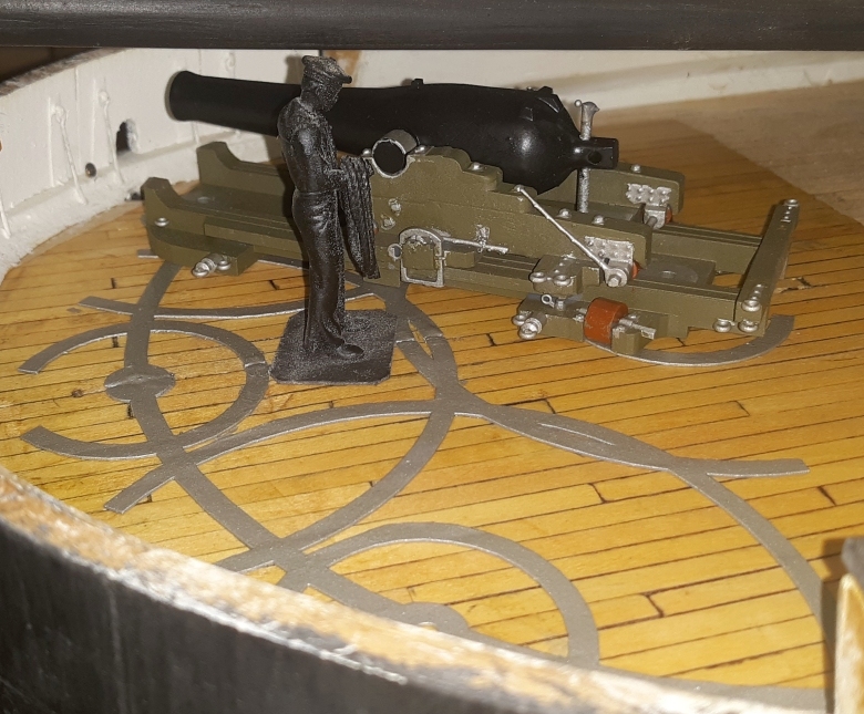
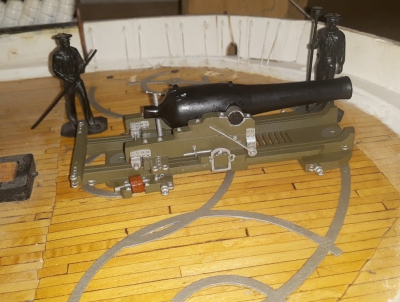
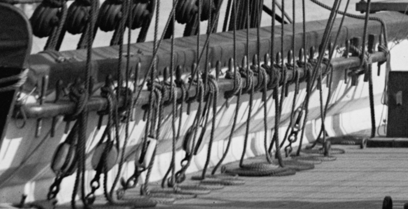
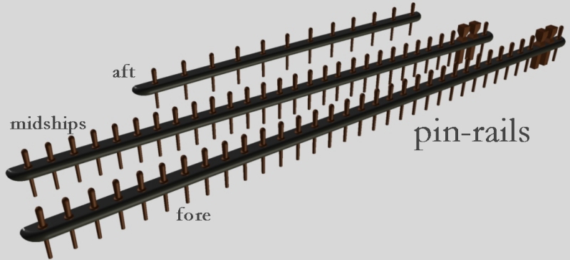
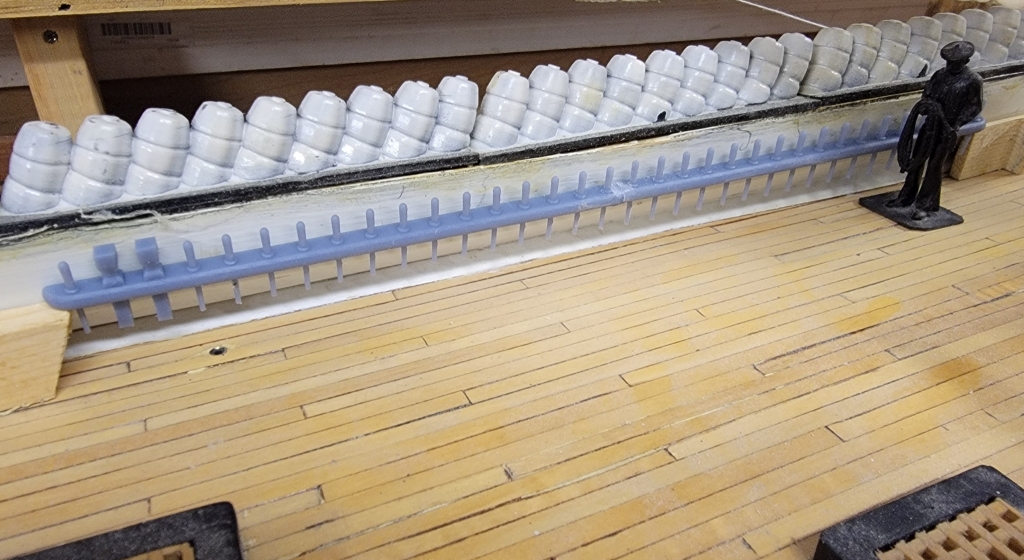
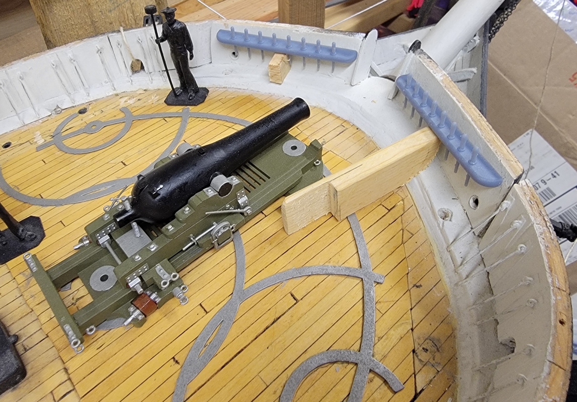
Previous Page | Next Page | Table of Contents click pictures for a larger version April 1 2024: My most recent project has been 3D modeling Naval guns from the 1850s through the 1870s. There's a "work-log" here on the site for it, if you're interested in the details. Part of this project is to model and print 1 of each gun Constellation carried over her carreer. While working on the 60# Parrott pivot gun, such as carried by the sloop of war Cumberland in her battle with the ironclad Virginia, I was thinking I should model Cumberland's other pivot gun next; a 10 inch Dahlgen. Looking for data on this gun, I found a drawing that John Dahlgren submitted in July of 1850 propossing frigates be armed with 6 10 inch pivots on their spar decks, and 26 9 inch carriage guns on the gun deck. The 10 inch gun in the drawing is exactly the same as the diagram for the Traversing Carriage and Slide from the Instructions of 1852, but Dahlgren changed the drawing's gun (except for the breech) to one of his guns. The Navy, by-the-way, didn't adopt his proposal, then. Instead they went with 2 10 inch pivot guns on the spar deck, and a mix of 8 inch shell-guns and 32# shot-guns. I went looking for the dimentions for a 10 inch Dahlgren and the best I could find was the maximum diameter was 29.1 inches, so I basically scalled the 11 inch tube I already made down to this diameter. I then used the Traversing Carriage diagram to make the carriage, and took the slide from my 10" shell-gun pivot and adjusted it to Dahlgrens drawing which was shorter, but the same in all other details. Spencer Tucker in his Arming the Fleet says the carriage was the same as that for for the Columbiads (the Traversing Carriage shown), but widened to accomodate the larger Dahlgren gun body. So this is the 3D model I made: While working on this, I noted that Dahlgren referred to the gun as: "10 inch gun ~ Pivot Carriage" and I'm wondering about Constellation. She was armed with two "10 inch guns on pivot carriages." I had gone with the gun from the Mississippi plan, dated June 23 1855 that shows a 10" gun of 86cwt (8600 pounds). Constellation was launched on August 26 1854, and commissioned on July 28 1855 - 4 and 5 years after Dahlgren's proposal. The timing of these documents, and not much more than a hunch, has me thinking Constellation had 10 inch Dahlgren pivots like her contempraries; Cunberland, Macedonian, Savannah, etc. While I try to nail this down somehow, I decided to go ahead and replace the model's pivots with Dahlgrens. This meant printing 3 of them at 1:36 scale; two for the model, and one for my Constellation Gun Sampler. Since the slide is shorter than the other pivot guns, I'll have to make new deck tracks as well. I only printed two of the guns, and in 3 parts each, rather than a single piece like the old pivots. The first one lost a roller, which I can fix, and the second one printed complete. April 3: With the guns printed, I started remodeling the deck-tracks, and printed them. I made them a more scale thickness than before. I printed them and scraped off the old tracks on the model's access hatches. There's more sanding to do to remove the scars of the old tracks, then some finish, before I can glue down the new tracks. April 4: The deck hatches were sanded as much as I dared to get the scares of the previous tracks removed, then given a couple of coats of the polyurethane finish the deck was originally done with. The 3D printed tracks were primed and painted in Testor's Flat Steel, and CAed to the hatches. On the forward hatch, a couple of ends of the track that over hang the hatch were cut off and glued to the deck on the model. April 21: Pivot guns painted and sitting in place; circles glued down on deck. December 8-10: Pin-Rails. An item actually holding up my starting to rig the model are the pin-rails. It'll be a real pain trying to install them once the lower rigging is in place. Building from the 3D model of the pin-rails at the base of thefore and main masts, I first built the aft rails.
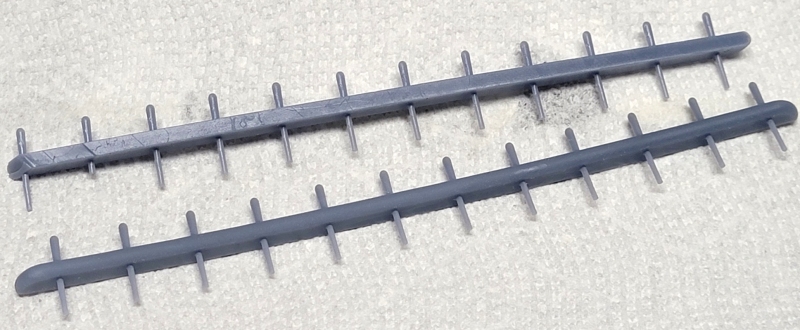
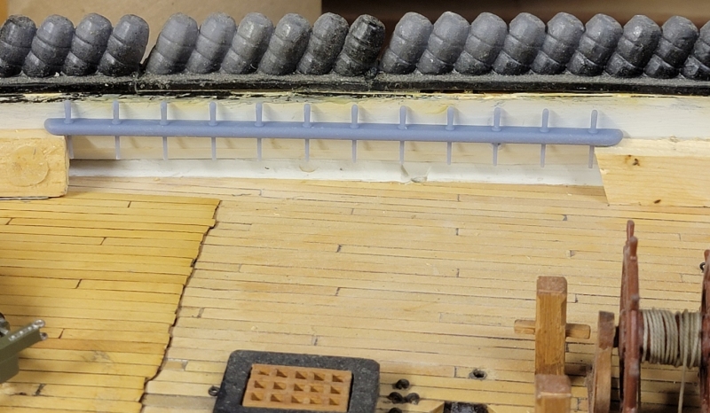
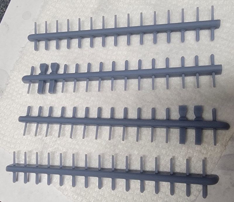
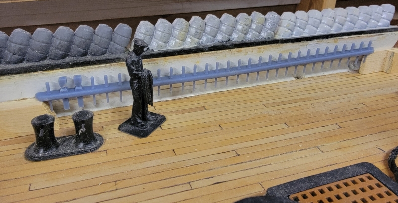
Printing them I noticed I forgot to account for the angle the bulwark leans inboard, and trying to shave or grind that angle in would make the rails too narrow, so I fixed the 3D model and printed again. These were perfect, and fit just right.
I had to make the model in two parts in order to fit in the printer. These also printed perfetly and got bonded together with rsin and a quick zap of UV light. The fore pin-rails were made much the same way, though they are a little longer.
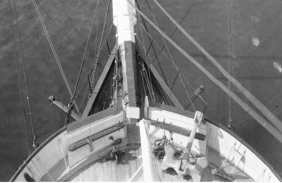
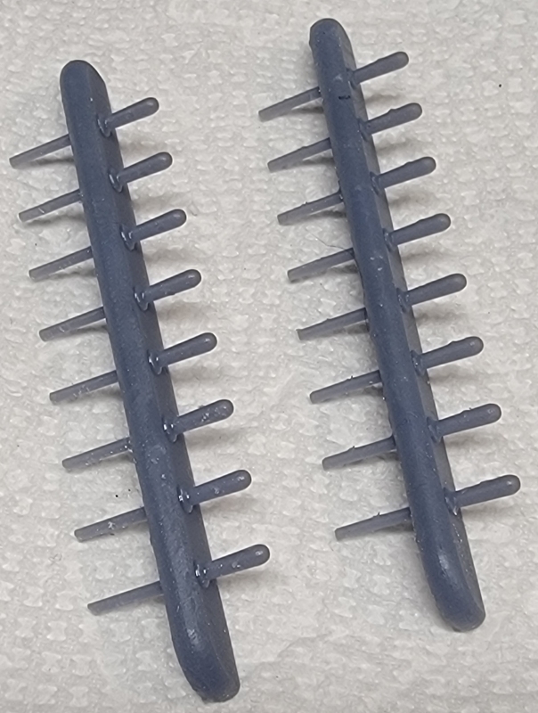
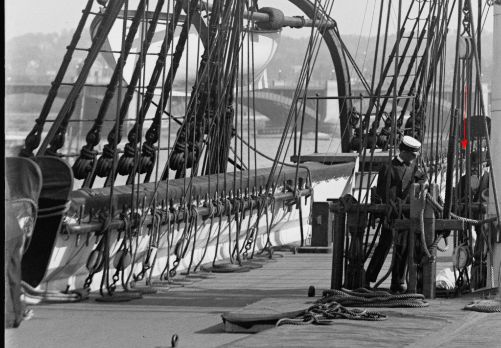
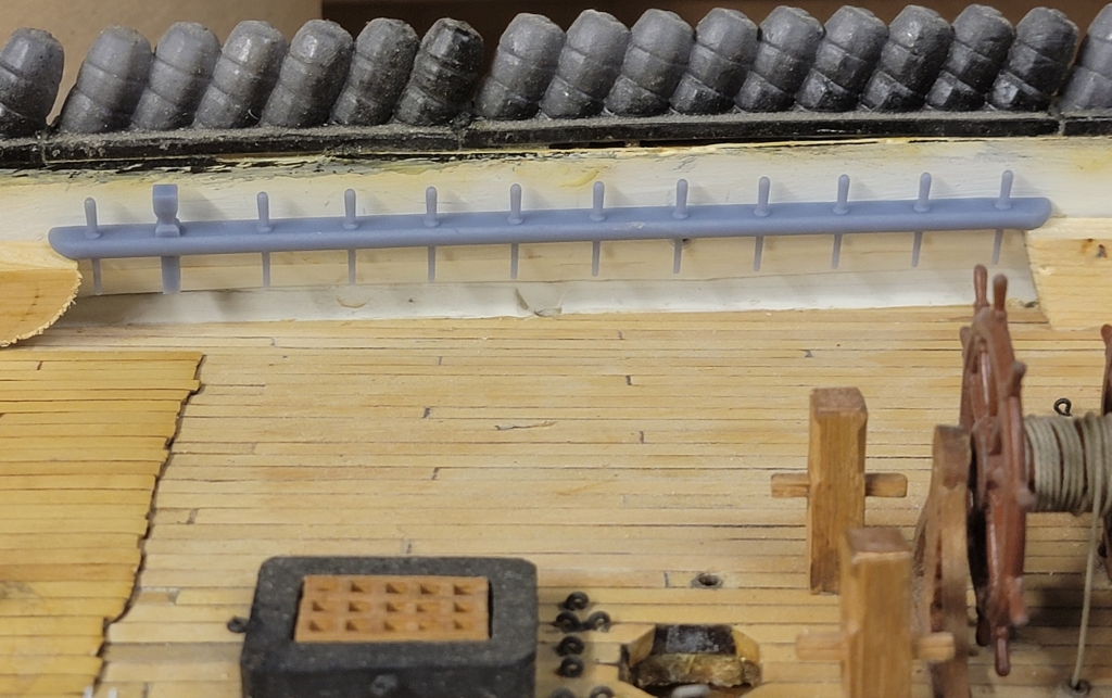
Finally, I think, are the pin-rails at the head on either side for the bowsprit. Here's an overhead view from 1926. December 13: While looking for other pin-rails back aft, I noticed a detail peeking between some lines on the aft pin-rail - it had one of those cudgel belaying pins as well! I also found it had more pins, closer spaced, than I had modeled, so I changed it, printed it, and here it is: |
||
 |
 |

