7/26/2014

 |
 |
|
Previous Page | Next Page | Table of Contents click pictures for larger versions Sliding Servos and Semaphore Arms
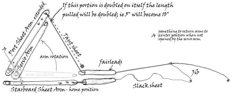
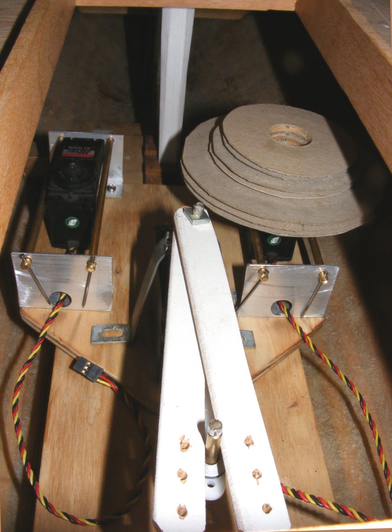
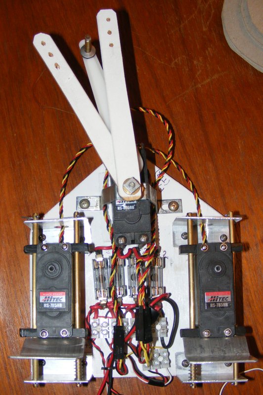
In preparation for the Museum Expo, a cobbled together version of the above was installed in Constellation to test. The arms each controlled a jib-sheet, port and starboard, while the servo arm controlled the driver sheet. Everything worked as expected though in light air when the sail doesn't pull the slack sheet out, it would be best to have a spring or some bungee to return the arms to the center position.
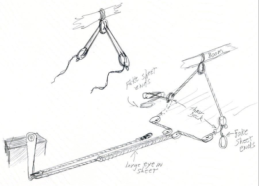
The mains'l sheet will be run in a way so as to look prototypical above deck
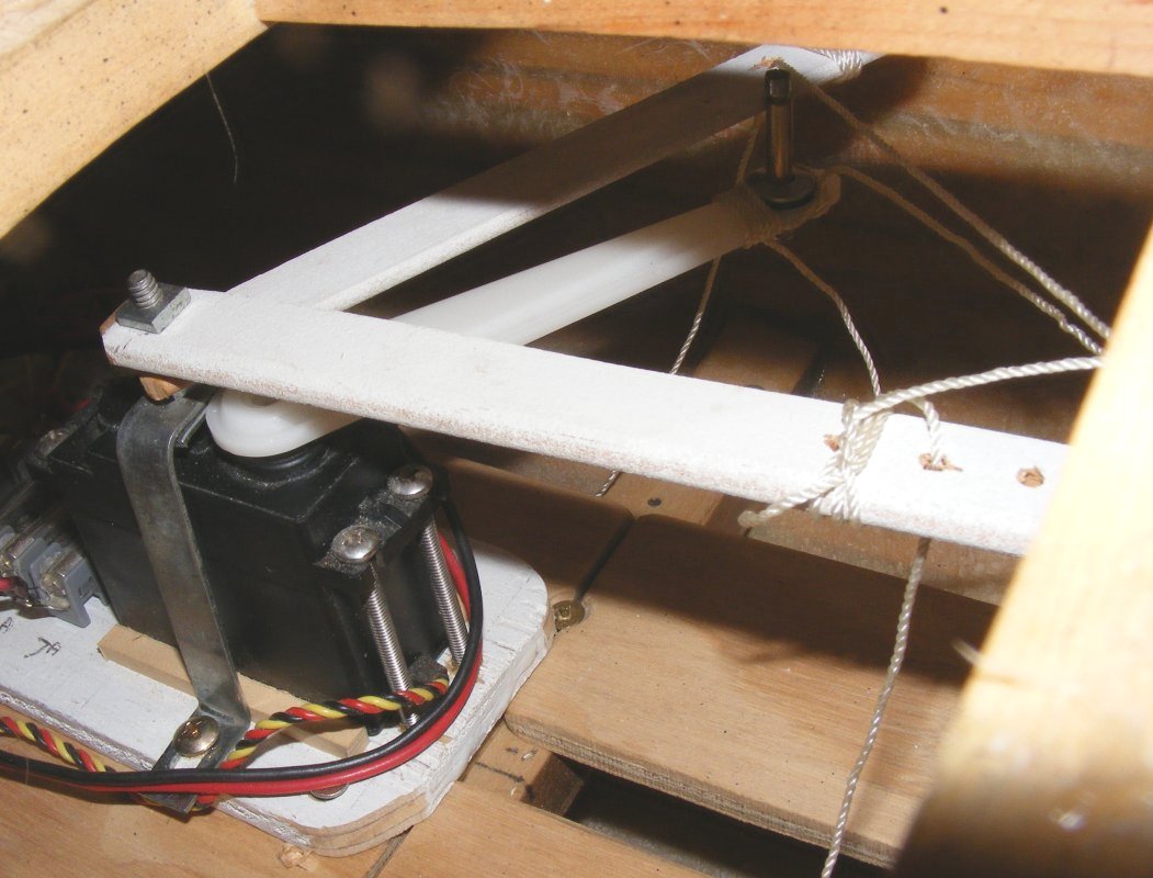
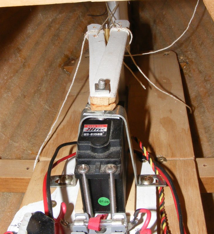
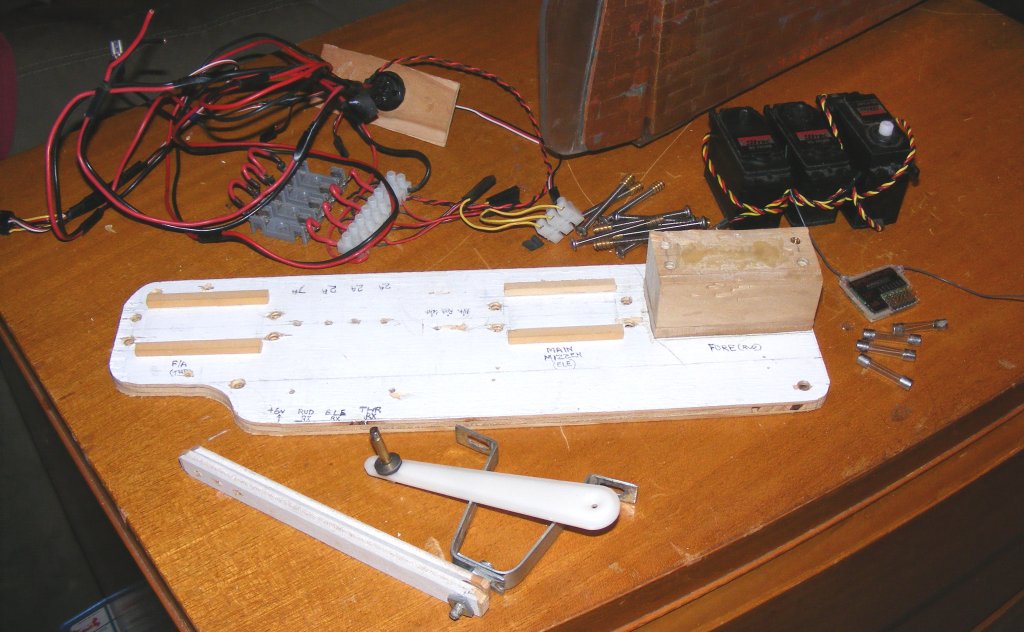
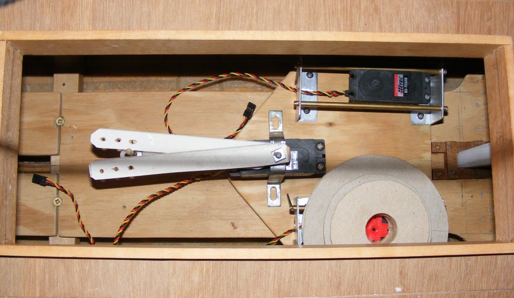
6/10: I disassembled the servo tray, salvaging the screw inserts and removing the wiring harness. Even though it's going to be replaced with a more efficient rig, it's a little melancholy dismantling something made five years ago.
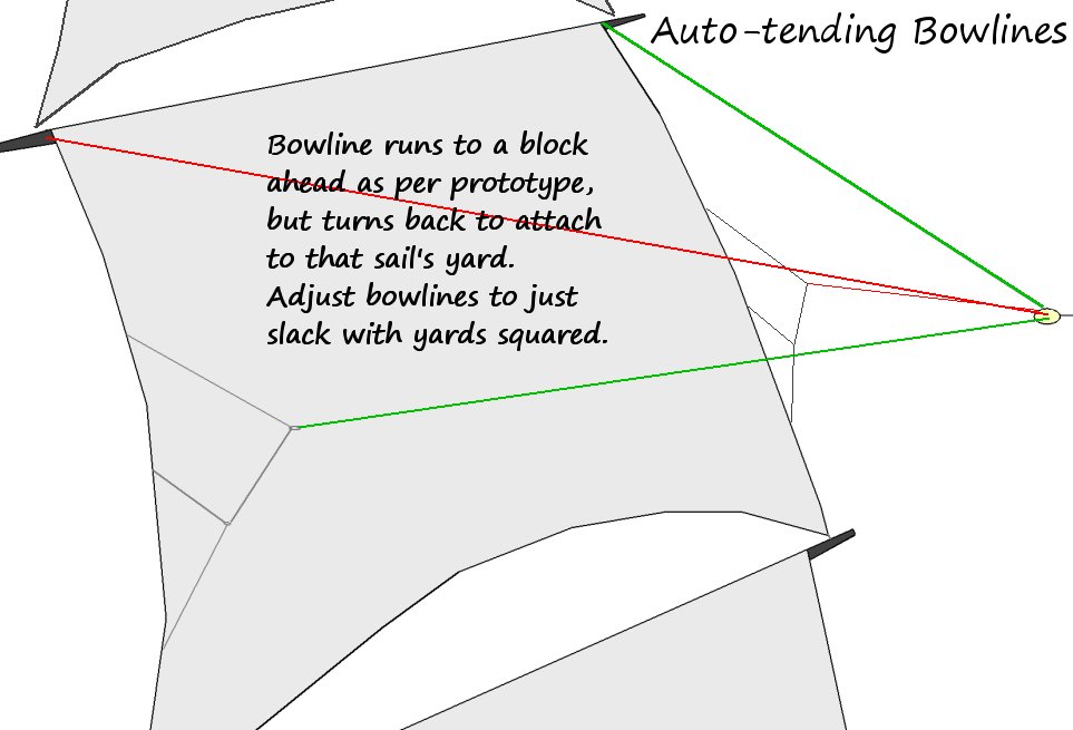
On an up-note; sailing the model gave me the impression that bowlines would help her upwind abilities. What I couldn't figure out was how to incorporate operating bowlines without adding mechanics, servos, radio channels, etc. With the model rigged and in front of me, I took the opportunity to play around with a couple of ideas and hit upon this:
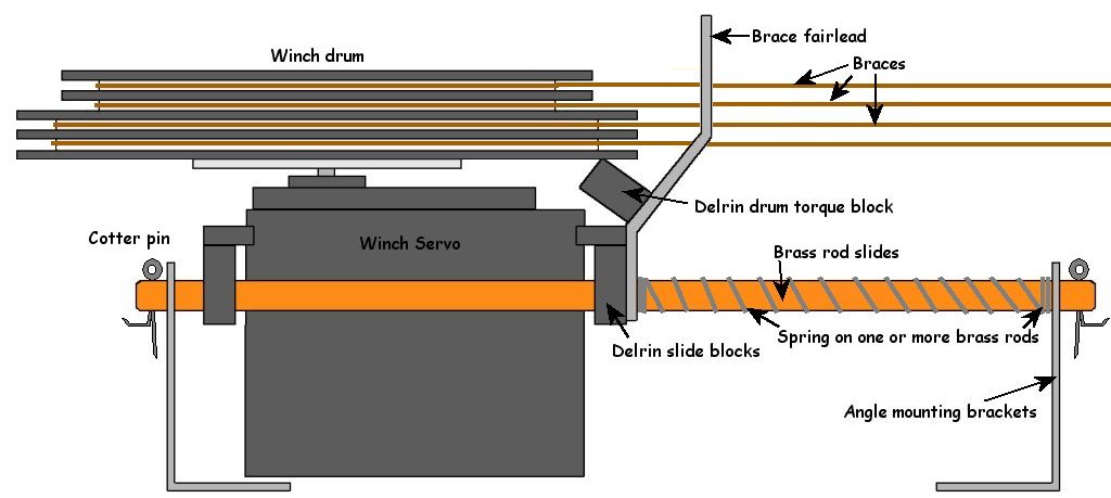
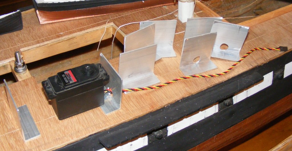
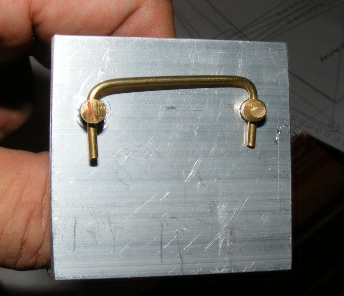
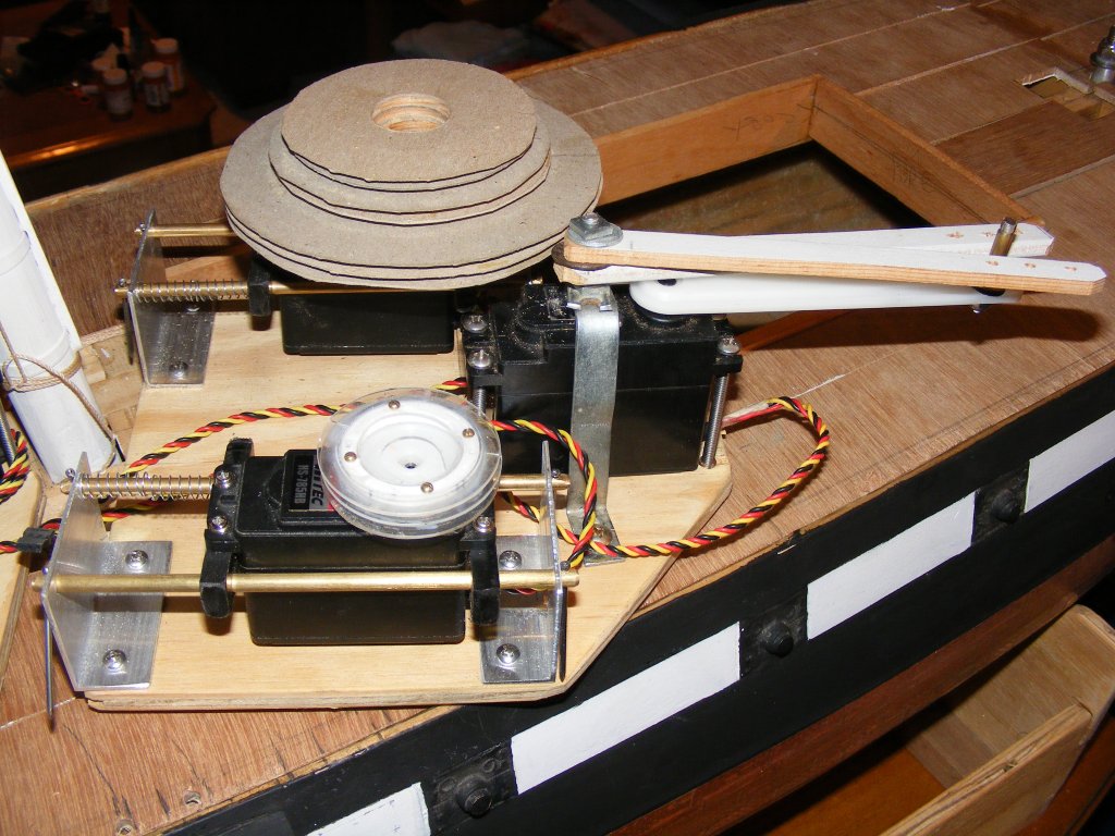
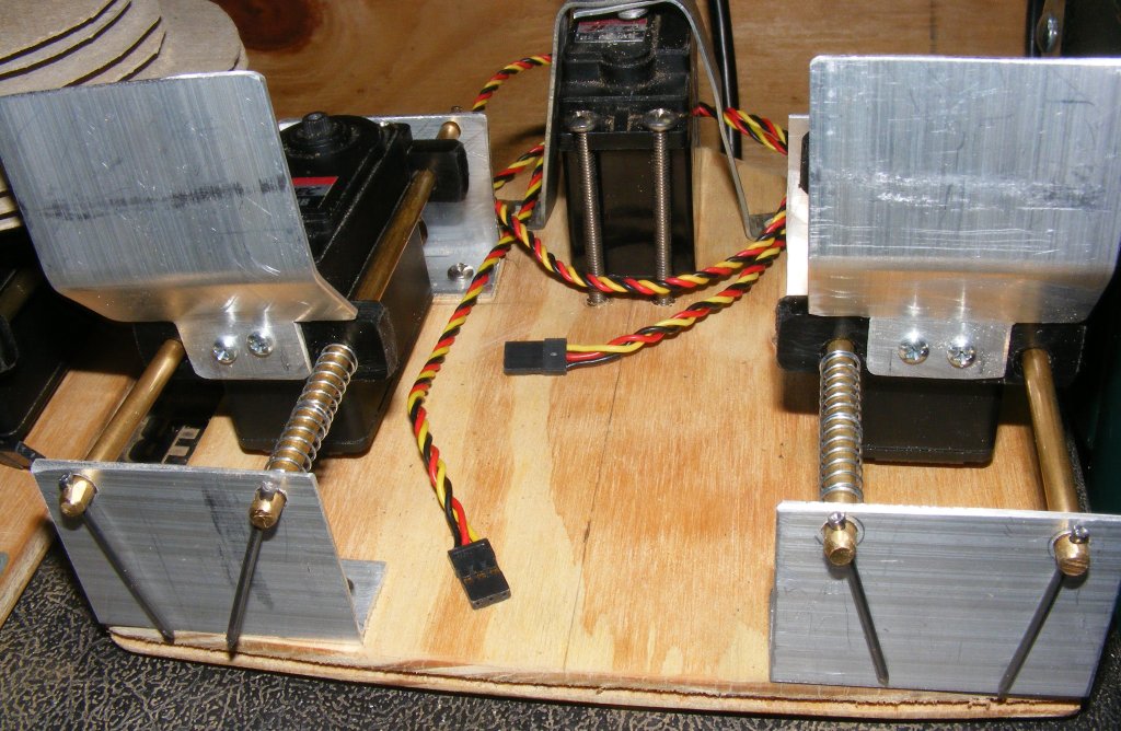
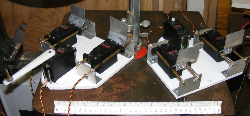
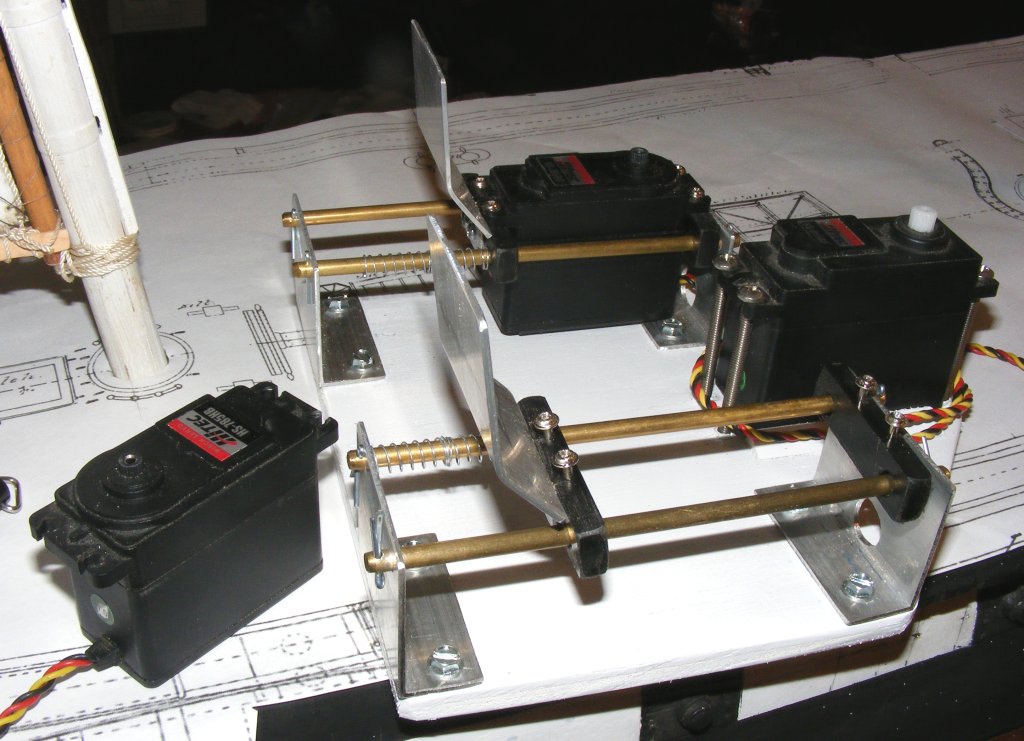
6/28: Got some 2" aluminum angle a couple of days back and today I cut the end brackets for the sliding winch assemblies from it. Each bracket is about 2" wide. One leg is cut down to 3/4" and the other to 1-3/4" so the fair-lead, which will be mounted on the servo, will clear the top of the bracket. Two holes were drilled 1-3/8" from the bottom and centers 1-3/8" apart for the rods the servos will slide on. This will leave about a 1/8" gap under the servo. The rods are drilled across their ends and a retaining pin is use to hold them in place.
Dan, master of the brig Syren, is sending me some Delrin plastic to make the servo mounting blocks. One that's done, these things will ready to install. 7/2: Went and got two 3 foot lengths of 3/16" brass rod, some brass tubing for fairleads, and some screws were aquired yesterday. Today all the rods were cut, drilled, and buffed. The servo trays were cut from 3.8" plywood and the end brackets mounted. Holes were drilled and the threaded inserts were installed for the sail-arm servo, and it was mounted 4p finish nails take the place of retaining pins for the moment, as the assembly is checked for fit in the hull. I still need to make the winch fairleads that mount on the servo.
7/5: Dan sent some 1/4" thick Delrin plastic sheet. From this I cut out 8 2" x 1/2" sticks. These were drilled for the rods to pass through, and on one edge for the servo mounting screws. The shop still isn't set up in a truely usable way, so getting everything precise was quite a chore. I had to cut two more sticks to replace one's I messed up. The slide blocks were mounted to the servos using the mounting screws that came with them. A few days later I cut 4 2" by 2-1/2" plates from the aluminum angle to make the fairleads. These were notched to clear the rods, the mounting holes were drilled to be inside the mounting screws of the servo. The plate was bent in a somewhat 'Z' shape to clear the edge of the winch drum, and they were mounted on the slide block on the end of the servo furthest from the winch with two #4 x 1/2" panhead screws nipped off to 1/4". The guide holes for the braces will get drilled when I find the winch drums that got packed away somewhere. Another nice thing about this set-up is if a servo needs to be replaced, take out 5 screws, (4 mounting and 1 for the winch drum), unplug it from the Rx and it's out. The servo isn't altered in any way.
As it turns out, it wasn't the servo, it was the operator - I didn't have the plug seated properly and the signal line wasn't making contact. With everything tested, I mounted it on the servo tray.
|
||
 |
 |