4/29/12
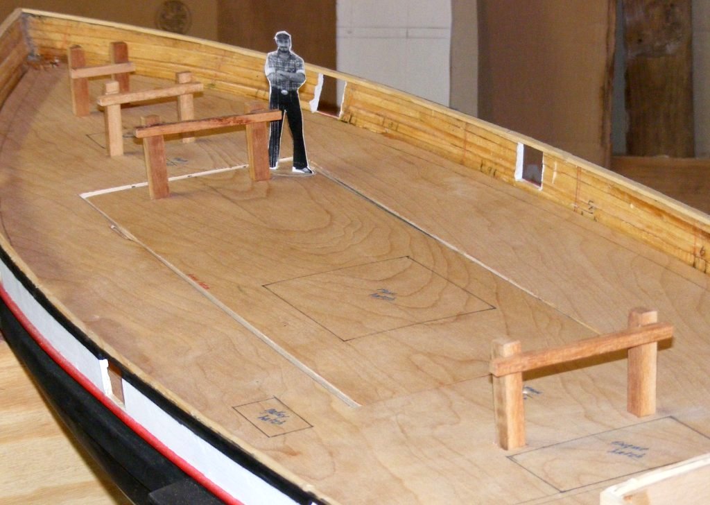
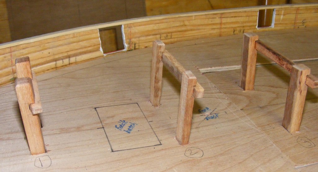
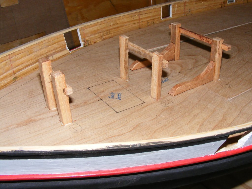
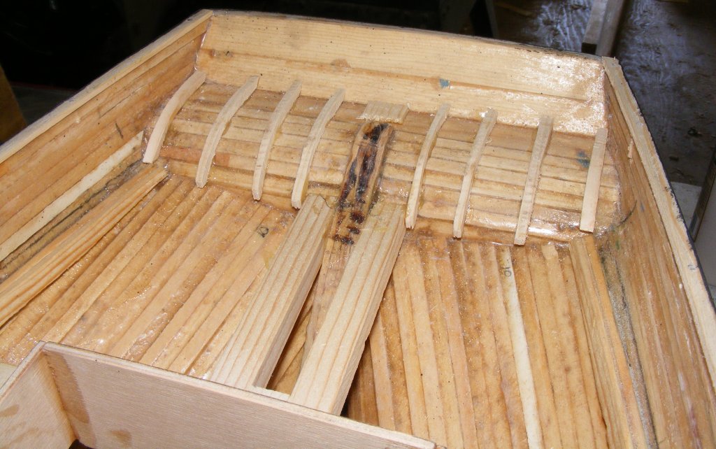
Previous Page | Next Page | Table of Contents 4/22/2012: Chomping at the Bitts Today I made the bitts from some wood Mark gave me that's very hard and may be some sort of Mahogany - it makes good bitts. They'll be epoxied into the subdeck and the planking will go around them.
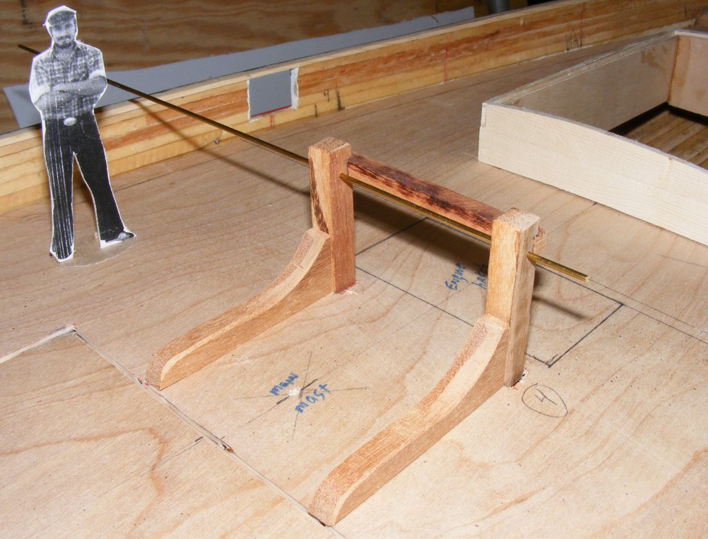
4/23: After making up the bits to the plans there were some details, especially on the aft riding bitt, with the windlass, that didn't seem right. The profiles show the windlass axle going through the post, but the deck plan shows it mounted forward of the post, on the knees. So, looking through all the photos and books, I found it did indeed go through the posts, and the crossbar stopped at the outer sides of the post.
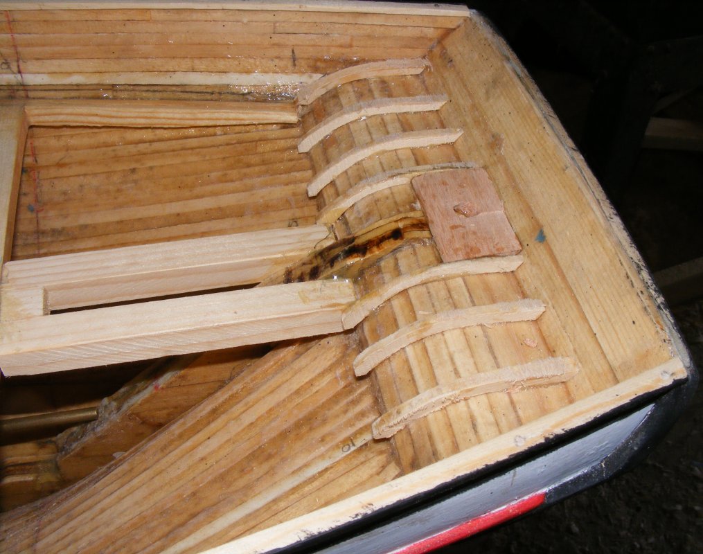
The bitts just fore and aft of the foremast had belaying pins added to them - I drilled them out for that. The forward one had actual pins, the aft one had spikes. Besides drilling little holes, I made the knees for the riding bitts just aft of each mast. The riding bitts will also get cheek blocks, mounted on the outside of their posts. The forward riding bitt's knees spans the access hatch seam. The hatch will have a tab that will fit into a slot up here, and a latching mechanism hidden in the false main hatch.
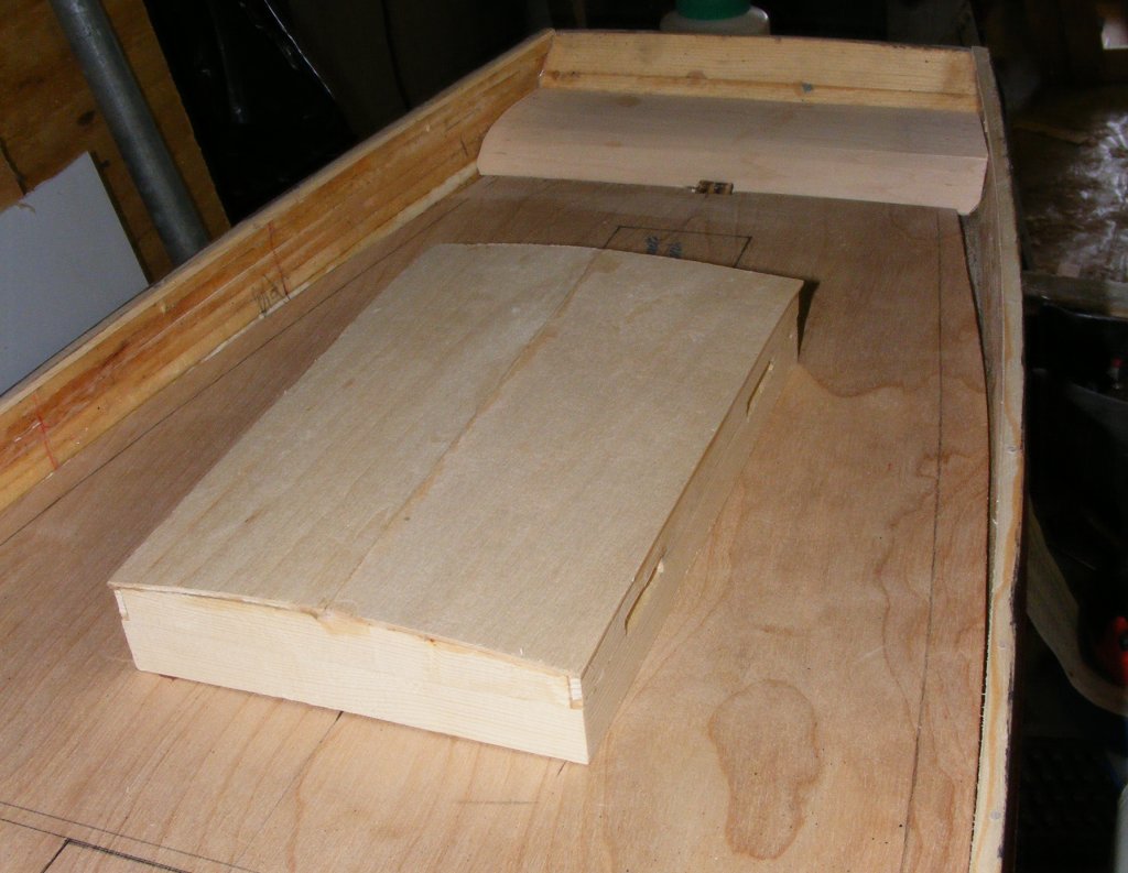
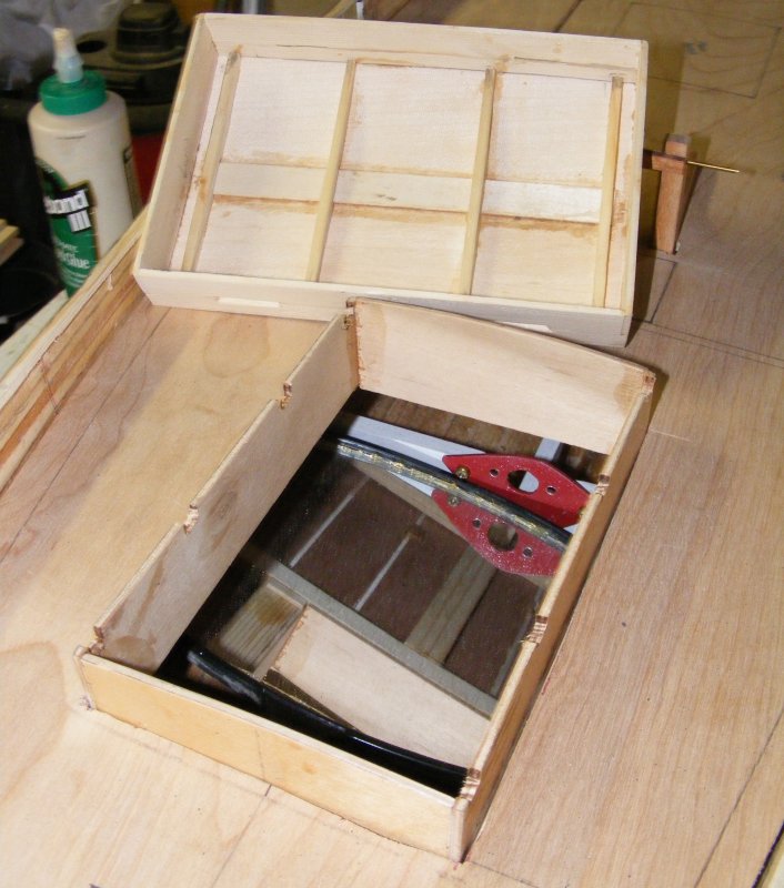
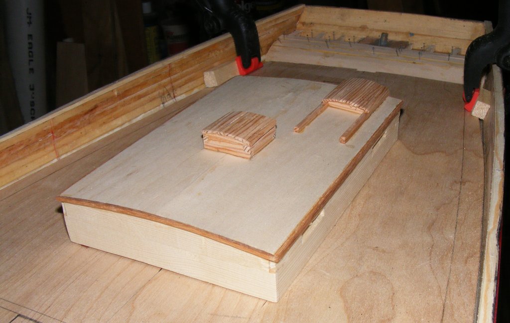
4/24: The framing in the counter got installed and decked over. The cabin also got it's roof and some internal structure. I milled up some of the Pride wood into little logs and made the skylight and next day the other cabin trimmings.
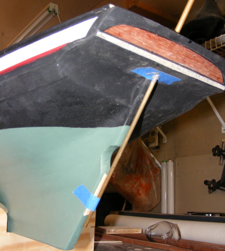
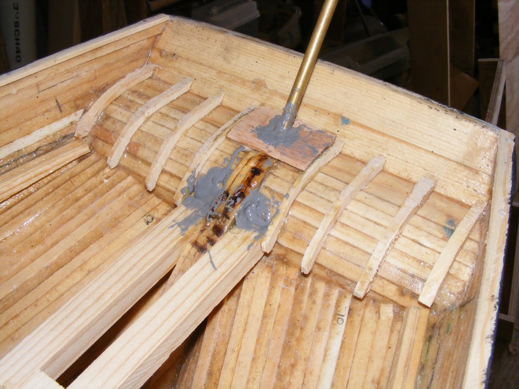
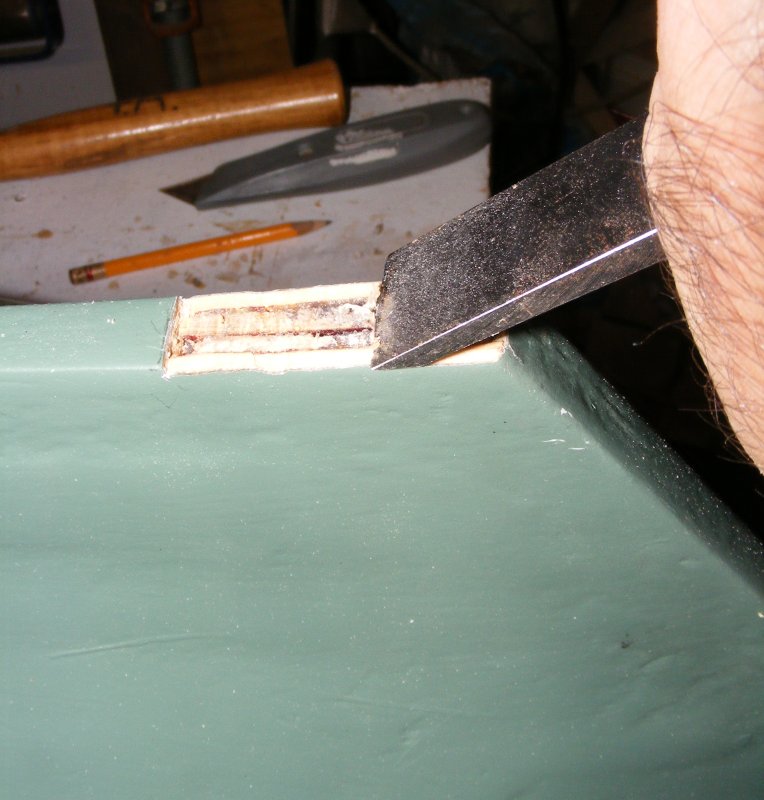
4/25: The Rudder The counter deck was only tacked on as I still had to drill the rudder shaft hole. I did a 1/16" pilot hole back when I did the propshaft hole, but both holes were covered up and larger diameter holes drilled. I pulled off the counter decking and installed an oak block to reenforce the hole. A 3/16" id brass tube was set in the slightly oversized hole using J.B.Weld.
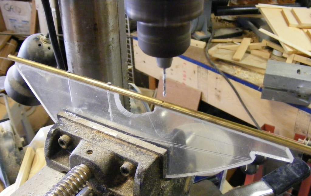
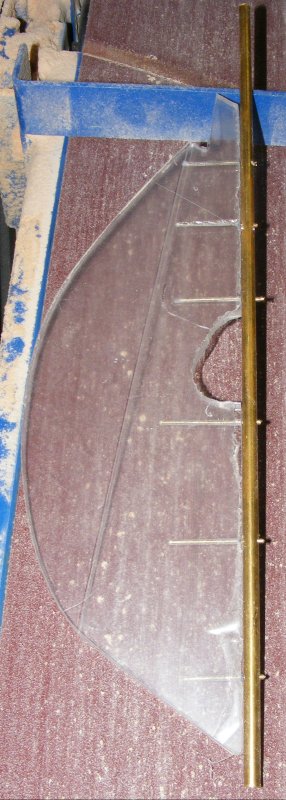
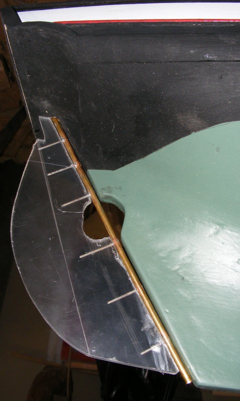
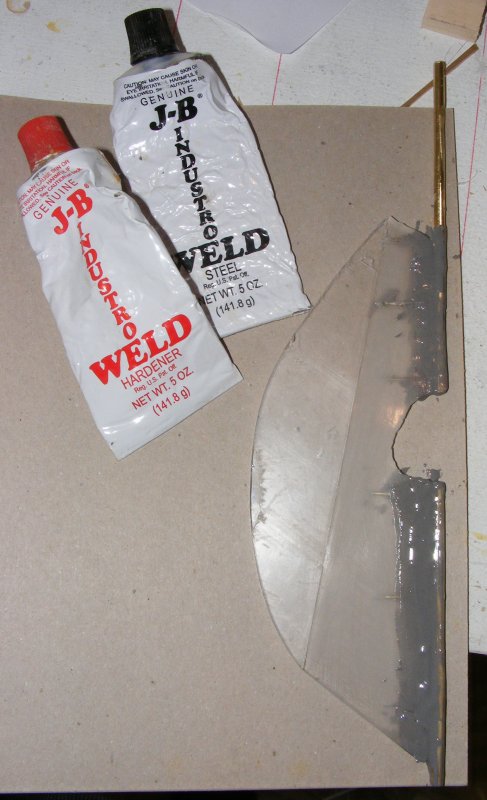
The rudder was cut from Plexiglas yesterday. Today I drilled the 3/16" brass rod that will be the rudder shaft for the 1/16" brass drift pins that will tie it to the rudder. Drilling through these holes, I drilled the rudder to match. The drifts were cut and everything dry fitted perfectly. The drifts were soldered to the shaft, filed and sanded smooth. I squirted CA adhesive into each hole and quickly set the rudder post in and then everything went to crap. The CA set up so fast I never got the drift pins all the way in. In trying to tap it in, the solder joints broke and I wound up peening the pins over on the shaft and the head of the rudder broke off.
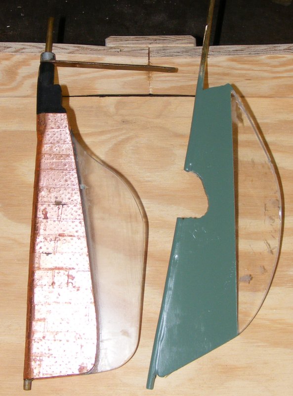
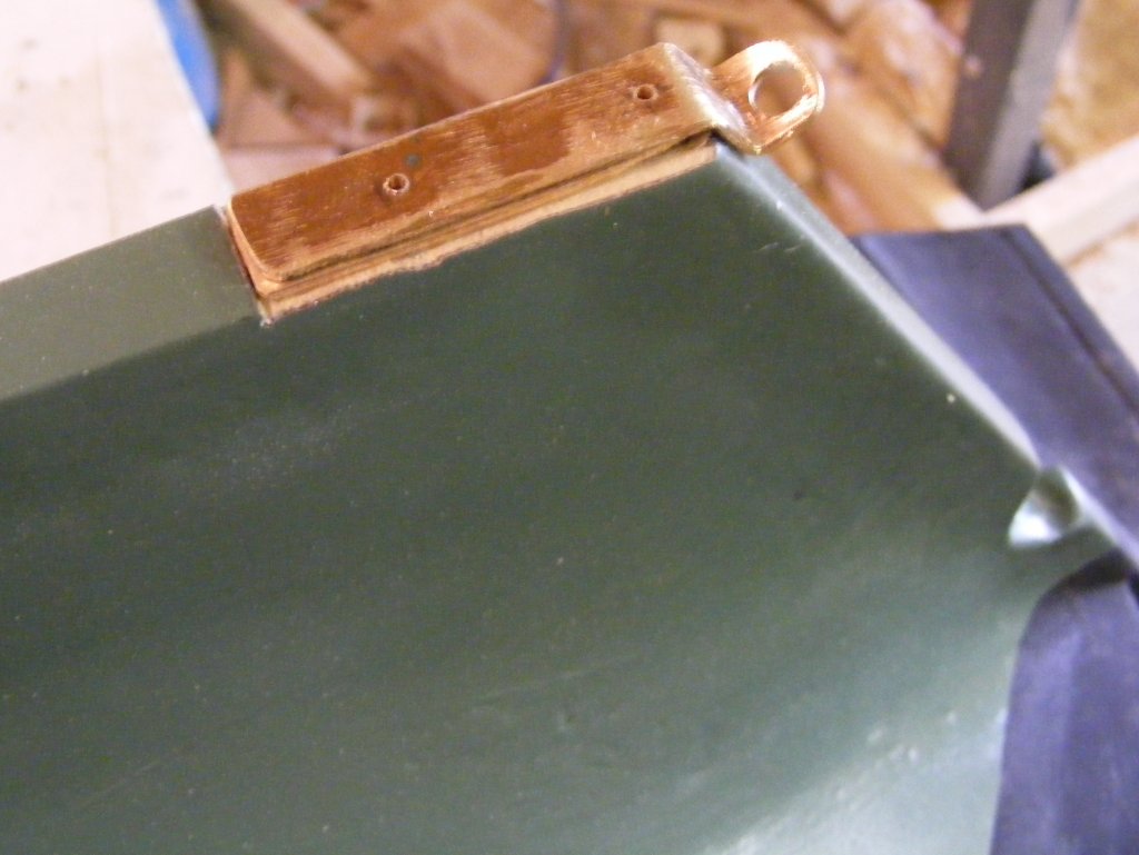
4/26: Finished up the rudder, repairing the broken off head and painting it. Then I started making the parts of the gudgeon plate. This plate is made in two parts; a mounting plate that is attached to the keel with wood screws and epoxy, and has holes threaded for two machine screws that hold the second part; the gudgeon plate that holds the heel of the rudder to the keel. It's made to be easily removed in case the rudder needs to be removed for some reason. I made the plate from the same heavy copper sheet Constellation's gudgeon plate was made from. Because of the rake of the stern post, it had to be bent into a 'Z' shape. I morticed the bottom of the keel so the mounting plate would sit flush with the bottom of the keel, and predrilled the plates. That all done, I had to get the brass screws to put it together.
|
||