5/10/12
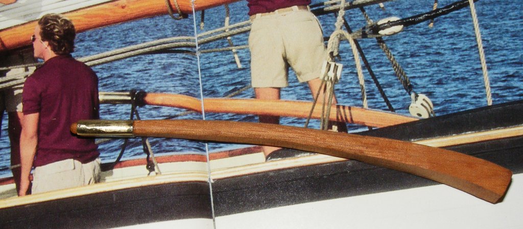
Previous Page | Next Page | Table of Contents 5/2/2012: Tiller I didn't have any tubing the right size, but I did have some sheet brass, so I rolled a bit of it onto a drill bit a little smaller than the end of the tiller and CAed that tube onto the end of the tiller. I files the seam away and gave the tiller a couple of coats of poly. I think it came out pretty good.
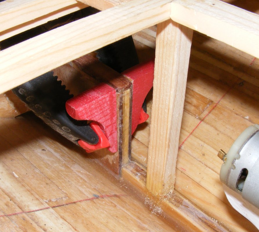
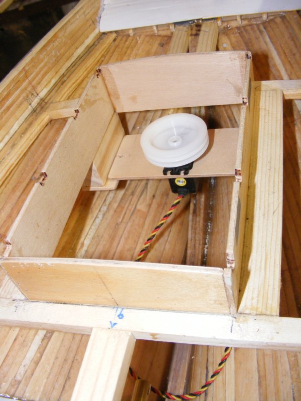
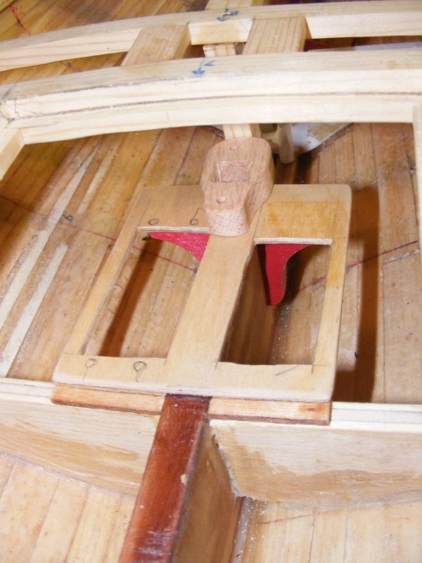
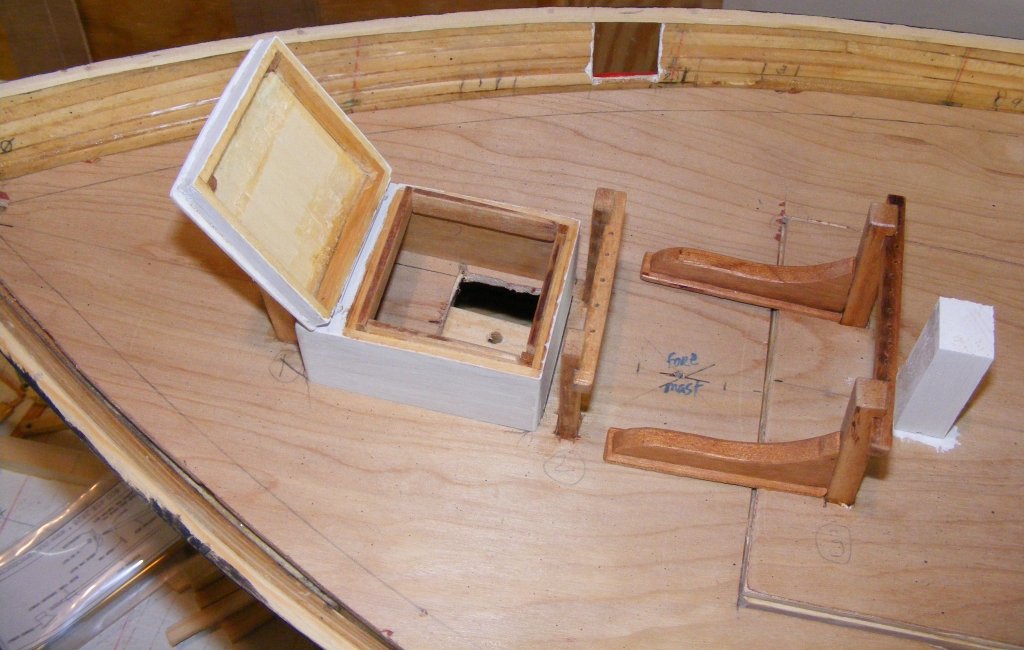
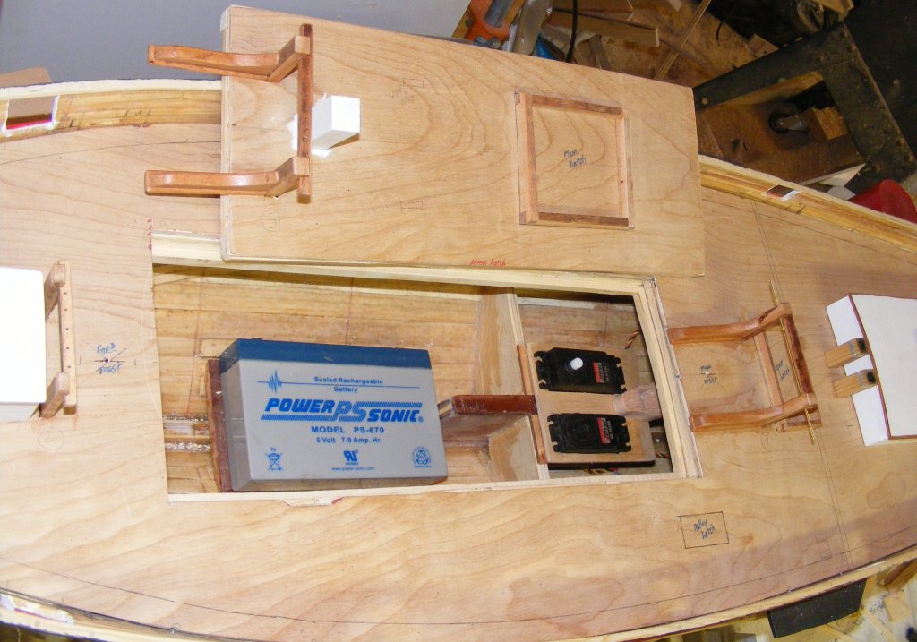
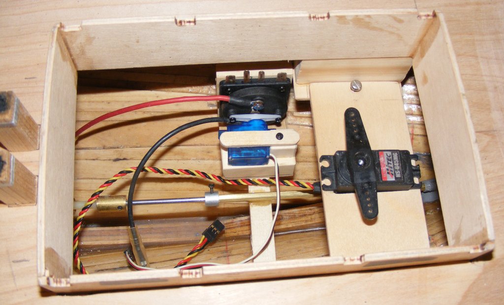
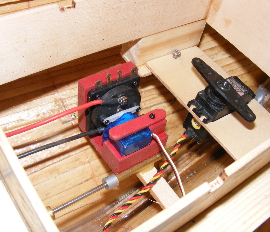
5/3: Mounting Servos I cut a servo tray from aircraft ply to hold one HS-815BB sail arm servo, and one HS-785HB winch servo on either side of the daggerboard trunk. I cut a pair of knees to support the aft end of the tray. These I painted red just because I have a can of red spray paint. The winch servo will run a shuttle line to control most of the sails. I think the main sheet will go on the arm. The main mast step will sit on the servo tray (that's the block with the square hole sitting between the servos). There's another knee installed on the post to further support the mast step.
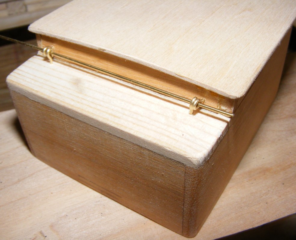
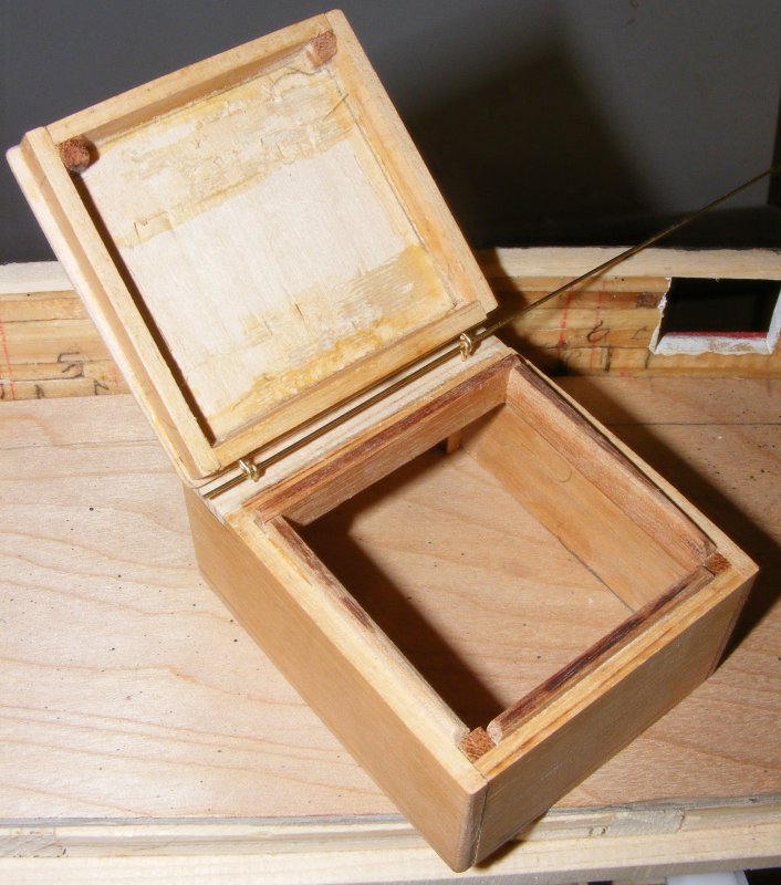
5/4: I made 4 eyes from .032" wire to make the focs'l hatch lid hinge. This will allow access to a rod that the forward sheave of the shuttle system with turn on.
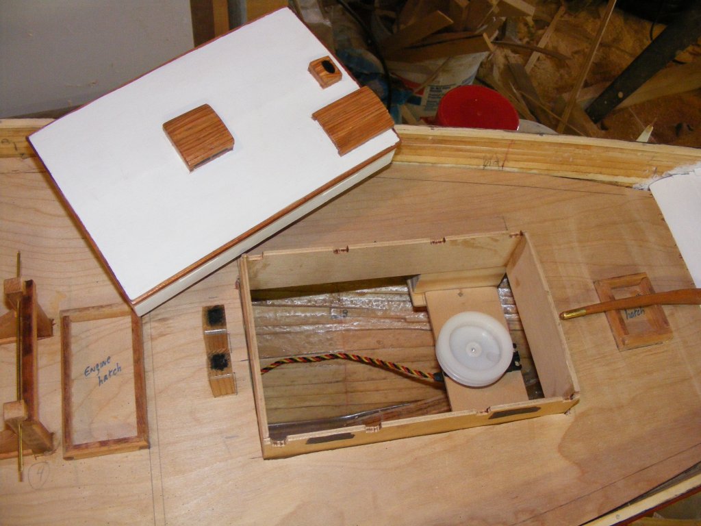
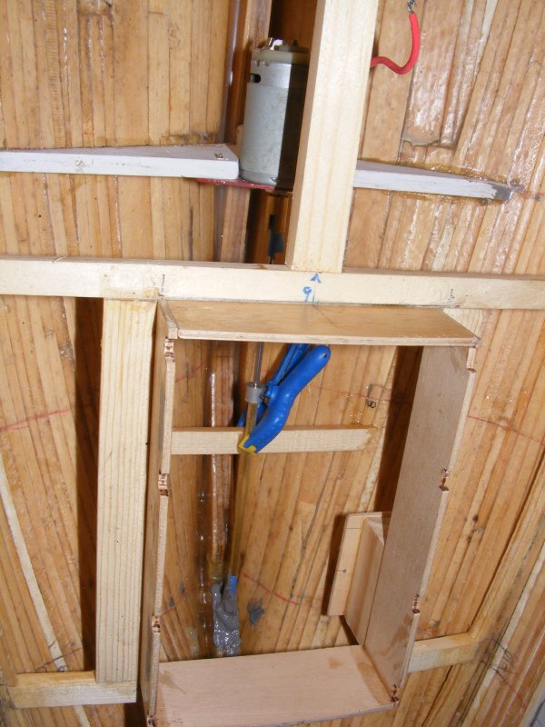
The rudder servo wound up being mounted in the cabin after all. It's tray is suspended on blocks about an inch below the deck. It's held by two screws so it's removable if I need to access the shaft for some reason, but I can get to the motor mount screws without removing it. I opted not to mount it foraward because with the winch and shuttle set up it would get too busy up there. I'm leaning toward using the winch servo drum instead of an arm to handle the rudder lines - I'll try both and see which works best.
The focs'l hatch got a coat of primer and a look at everything with the hatches open while I contemplate setting up the shuttle system.
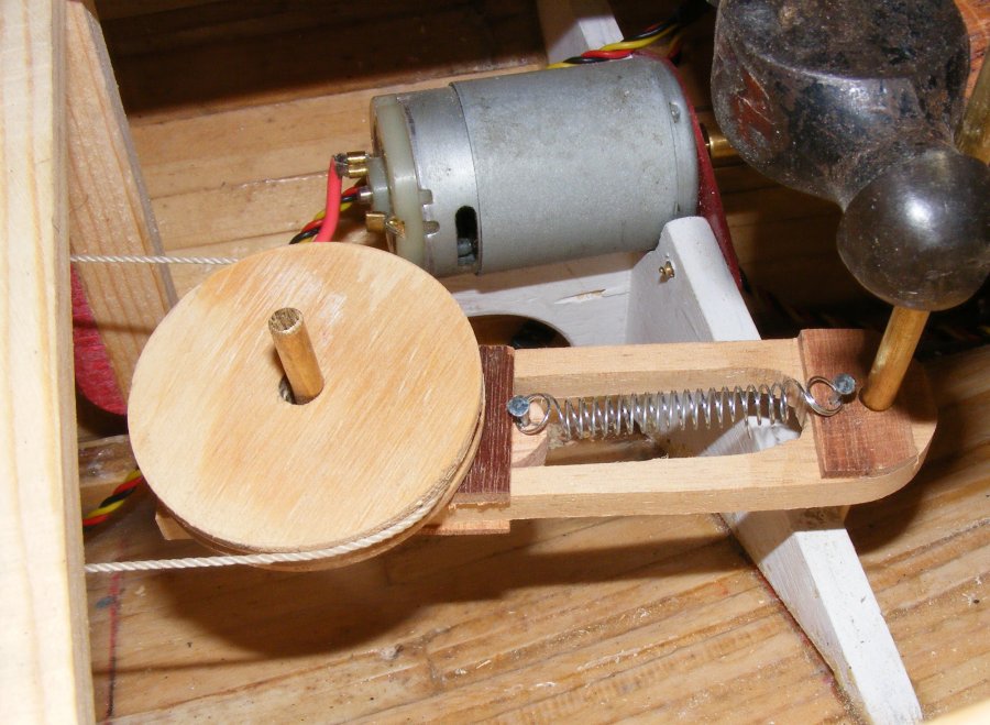
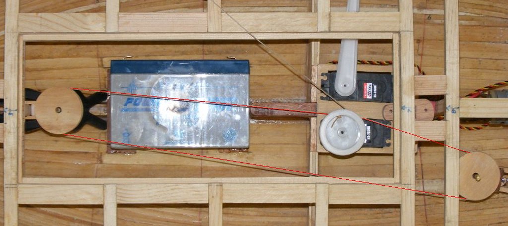
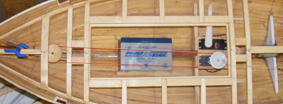
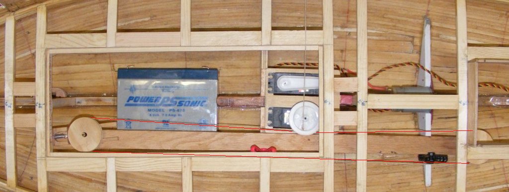
5/6: Using a couple of cut-outs from the hole saw as pulleys, I made a quick and nasty spring tensioner and set up a few arrangements for the shuttle sail control system.
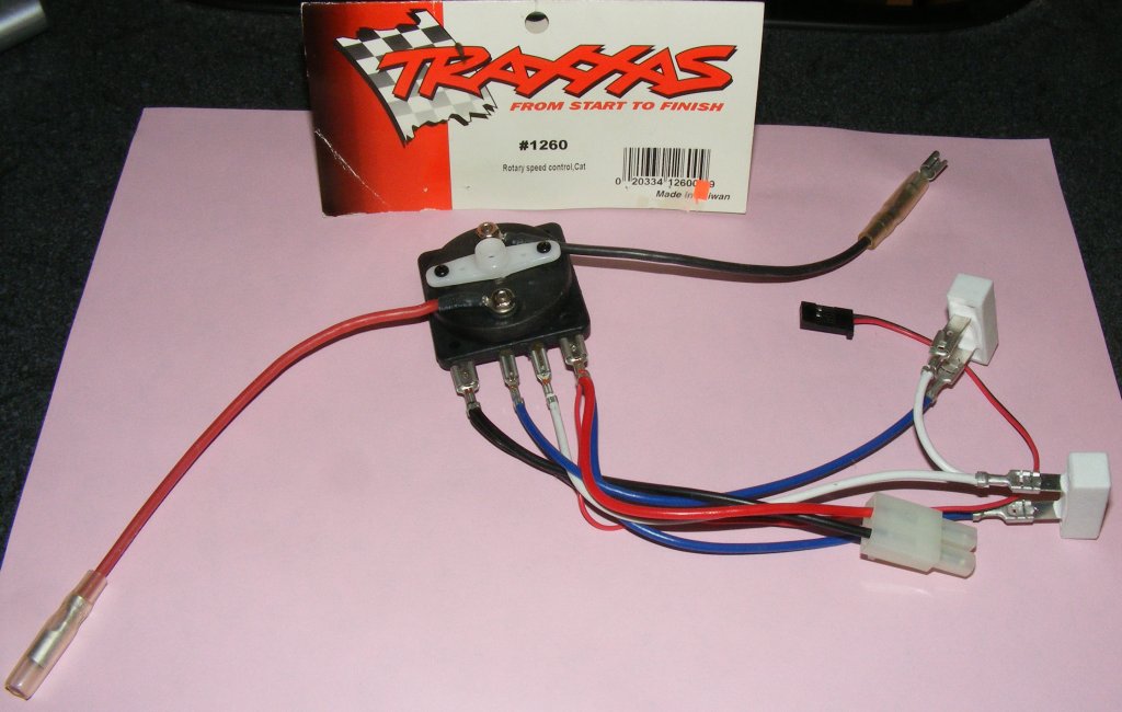
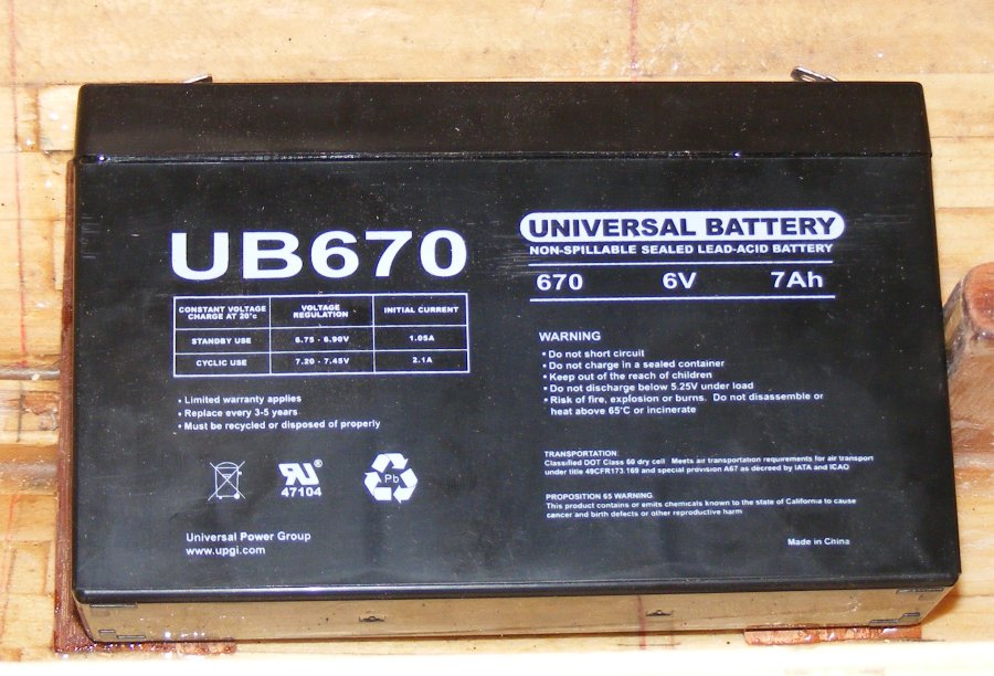
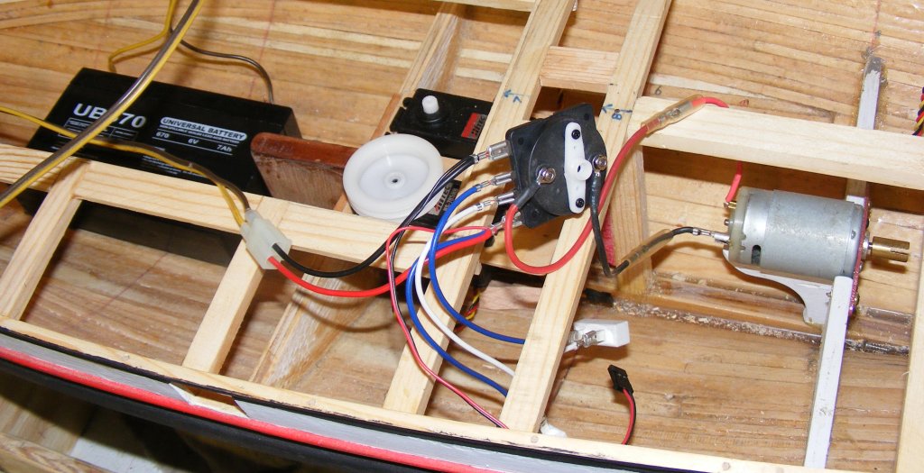
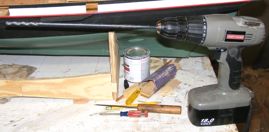
So, I think I'm going with set-up #3. I have to verify the distance of the pulleys, based on how far the winch will move the line, and I'll probably use a length of aluminum channel as the beam to mount it all on. 5/7: POWER! The speed control arrived in today's mail, a Traxxas #1260 rotary type. I had to try it, of course, but I needed a battery. While out on a battery hunt, I picked up an 18" long 1/4" drill bit to open the stuffing box hole in the stern post.
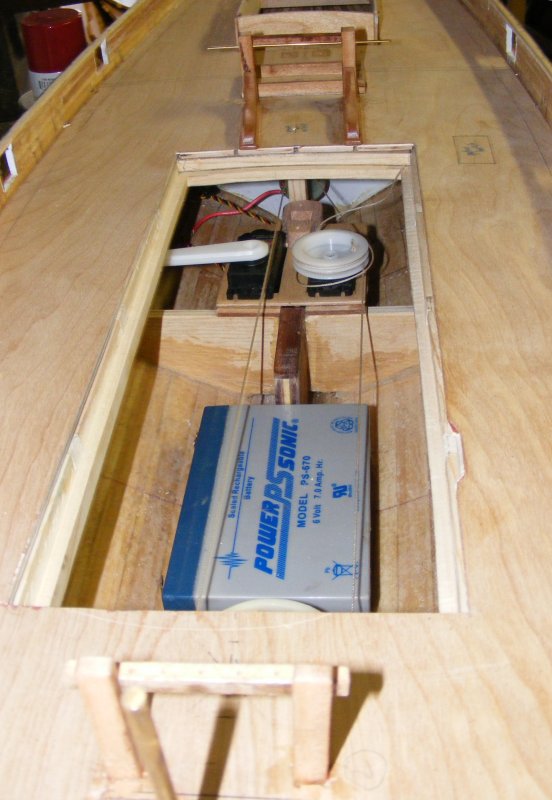
Everything connected, I gave the motor it's first test in the boat with a brand new battery and a speed control.
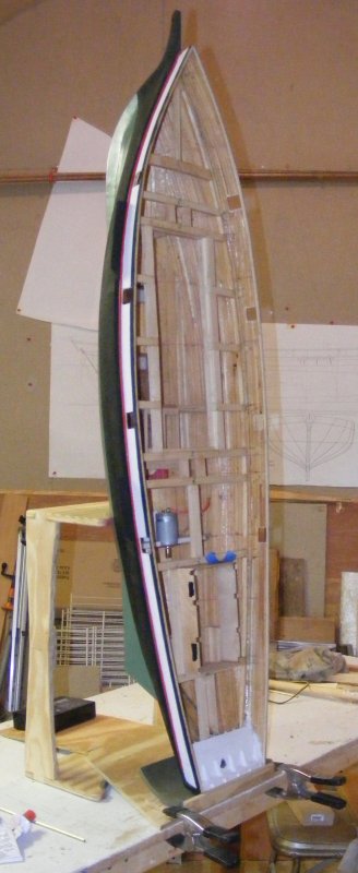
The hole drilled, I trial fitted the stuffing box and shaft. I taped over it outside so the J.B.Weld wouldn't run out and stood the hull up on it's transom so gravity would help. I put some JBW into the hole. The end of the stuffing box was taped to keep things out, the end to be buried was rolled in some JBW and slide into the sternpost and punched through the tape so it extended 1/4" outside the hole.
5/8: The speed controller needs a servo to operate it, for which I enlisted a micro-servo I have laying about. I needed to mount it in the hull in a way I could get at it and remove it if necessary. I built a tray for it to mount on from aircraft block and some pine blocks. The popsicle stick looking part keeps the servo from twisting, but can be turned aside and with two screws removed, the whole apparatus can come out. It's pictured on the stuffing box brace which is where it will probably live as the easier to get at while being out of the way. Now I have to figure out what to do with the two ceramic resistors that came with the speed control.
5/9: The speed control was married to a micro servo and mounted in the hull; wired up to motor and Rx and tested. Everything worked great so it was on to geometry class.
I found some simple idea for handling all the over lapping sails on this little racehorse so Mark and I spent a lot of time rigging up mock-ups and trying to see if it would work. We got to the point were I need to rig up a test rig to really see if it'll function. |
||